Programming Manual
Page
Foreword
FX Series Programmable Controllers
FX Series Programmable Controllers
FAX Back Combined Programming Manual J
FX Series Programmable Controllers
Software Warnings
Hardware Warnings
FX Series Programmable Controllers
Contents
STL Programming
Applied Instructions
Rotation And Shift Functions 30 to
External FX Serial Devices Functions 80 to
Execution Times And Instructional
10-1
Viii
FX Series Programmable Controllers
Chapter Contents
Overview
Introduction
What do You Need to Program a PLC?
What is a Programmable Controller?
Current Generation CPU all versions
Special considerations for programming equipment
Manual name Number FX Base Unit Hardware
Assocciated Manuals
Manual name Number FX DU, GOT and DM units
Memo
Basic Program Instructions
FX Series Programmable ControllersBasic Program Instructions
Outline of Basic Devices Used in Programming
What is a Program?
Detailed device information
Example
How to Read Ladder Logic
OUT instruction
Load, Load Inverse
Program example
Out
Timer and Counter Variations
Last coil effect
Use of dual coils
Double Coil Designation
Peripheral limitations
And, And Inverse
ORI
Or, Or Inverse
Single Operation flags M2800 to M3071
Load Pulse, Load Trailing Pulse
LDF ANF OUT
Pulse, And Trailing Pulse
ORF ORB
Or Pulse, Or Trailing Pulse
Batch processing limitations
Or Block
Sequential processing limitations
ANB
Block
MPS, MRD and MPP usage
13 MPS, MRD and MPP
Multiple program examples
MCR
Master Control and Reset
Nested MC program example
Resetting timers and counters
Set and Reset
Retentive timers
Timer, Counter Out & Reset
16.1Basic Timers, Retentive Timers And Counters
Availability of devices
Bit counters
Normal 32 bit Counters
High Speed Counters
Leading and Trailing Pulse
PLF
Usages for INV
Inverse
No Operation
No Operation
Program scan
20 End
Memo
STL Programming
FX Series Programmable ControllersSTL Programming
General note
What is STL, SFC And IEC1131 Part 3?
Each step is a program
How STL Operates
Look Inside an STL
Combined SFC Ladder representation
How To Start And End An STL Program
Embedded STL programs
Activating new states
Terminating an STL Program
Initial Steps
Returning to Standard Ladder
Moving Between STL Steps
Using SET to drive an STL coil
OUT is used for loops and jumps
Using OUT to drive an STL coil
Out is used for distant jumps
Basic Notes On The Behavior Of STL programs
Rules and Techniques For STL programs
T001 K20 K50
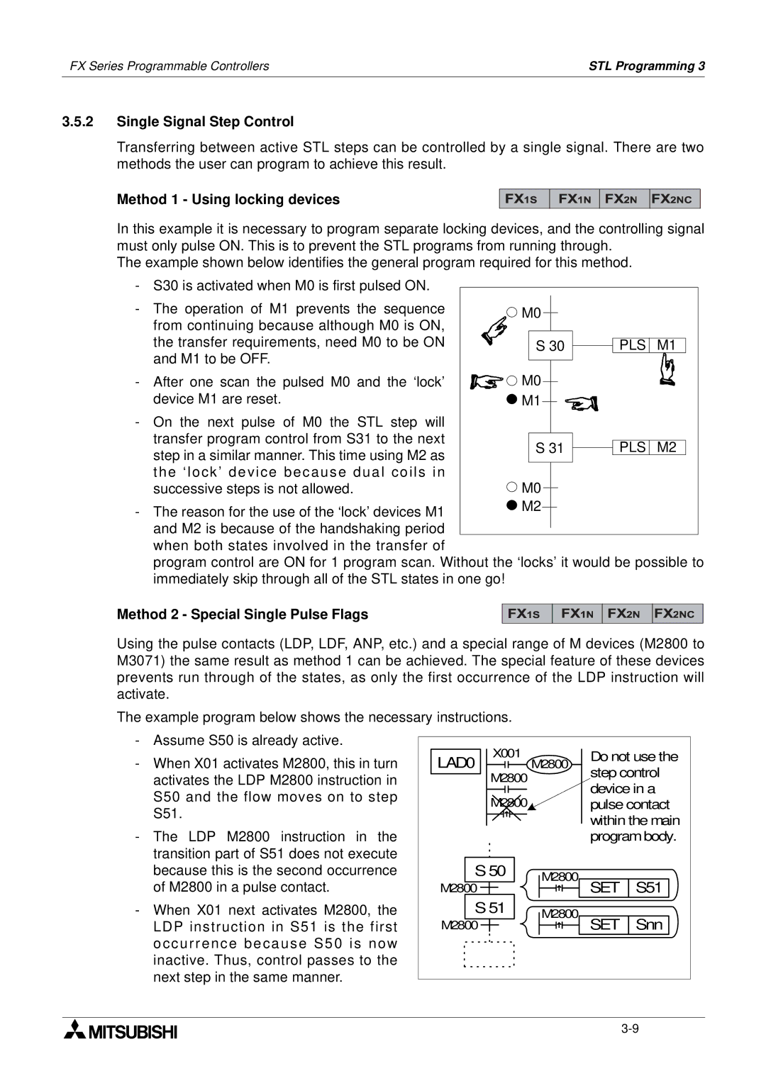
Method 1 Using locking devices
Single Signal Step Control
Method 2 Special Single Pulse Flags
Using ‘jump’ operations with STL
Restrictions Of Some Instructions When Used With STL
Restrictions on using applied instructions
STL OUT SET
Using STL To Select The Most Appropriate Program
Limits on the number of branches
Using STL To Activate Multiple Flows Simultaneously
Limits on the number of branches
Instruction Format
General Rules For Successful STL Branching
General Precautions When Using The FX-PCS/AT-EE Software
Simple STL Flow
Programming Examples
SET STL
Identification of normally closed contacts
Selective Branch/ First State Merge Example Program
Points to note
Full STL flow diagram/program
Advanced STL Use
Devices in Detail
FX Series Programmable ControllersDevices in Detail
Inputs
Configuration details
Available devices
Device Mnemonic
Device Mnemonic Y
Outputs
Alias O/P
Device Mnemonic M
Auxiliary Relays
General Stable State Auxiliary Relays
External loads
Battery Backed/ Latched Auxiliary Relays
Special Single Operation Pulse Relays
Special Diagnostic Auxiliary Relays
Device Mnemonic S
State Relays
General Stable State State Relays
PLC FX 1S FX 1N FX 2N
Battery Backed/ Latched State Relays
Monitoring STL programs
Assigned states
STL/SFC programming
IST instruction
Annunciator Flags
Jumping to the end of the program
Pointers
Device availability
Device Mnemonic P
Additional applied instructions
Interrupt Pointers
Nested levels
Pointer position
Rules of use
Timer Interrupts
Input Interrupts
Disabling high speed counter interrupts
Driving special auxiliary relays
Additional notes
Disabling Individual Interrupts
Constant H
Constant K
Device Mnemonic K
Example device usage N/A
Timer accuracy
Timers
Device Mnemonic T
Selectable Timers
General timer operation
Driving special auxiliary coils
Retentive Timers
Using timers in interrupt or ‘CALL’ subroutines
Timers Used in Interrupt and ‘CALL’ Subroutines
Internal timer accuracy
Timer Accuracy
Condition
Counters
Setting ranges for counters
High speed counters
Device Mnemonic C
General/ Latched 16bit UP Counters
Battery backed/latched counters
Selecting the counting direction
Battery backed/ latched counters
General/ Latched 32bit Bi-directional Counters
Further uses None
Basic high speed counter operation
Basic High Speed Counter Operation
Driving high speed counter coils
Counter Speeds
Input assignment
Availability of High Speed Counters
Calculating the maximum combined counting speed on FX1S
Setting range
Device specification
Direction setting
Using the SPD instruction
RST
Device size
11.5 2 Phase Bi-directional Counters C246 to C250
11.6 A/B Phase Counters C252 to C255
Device Mnemonic D
Data Registers
Example device usage None
Data retention
Data register updates
General Use Registers
Use of diagnostic registers
Using the FX2-40AW/AP
Battery Backed/ Latched Registers
Special Diagnostic Registers
Writing to file registers
Special caution when using FX1S
File Registers
Program memory registers
Uses
Externally Adjusted Registers
Use of Modifiers with Applied Instruction Parameters
Index Registers
Device Mnemonic V,Z
Available forms
Modifying a Constant
Using Multiple Index Registers
Misuse of the Modifiers
Bit Devices, Individual and Grouped
Bits, Words, BCD and Hexadecimal
Assigning I/O
Moving grouped bit devices
Assigning grouped bit devices
Interpreting Word Data
Word Devices
FX Series Programmable Controllers
Word Data Summary
Binary Coded Decimal value= Error
Inverted7 Additional1
14.4 Two’s Compliment
Some useful constants
Floating Point And Scientific Notation
Scientific Notation
Floating Point Format
FLT