FX Series Programmable Controllers | Basic Program Instructions 2 |
2.5Out
FX1S | FX1N | FX2N | FX2NC |
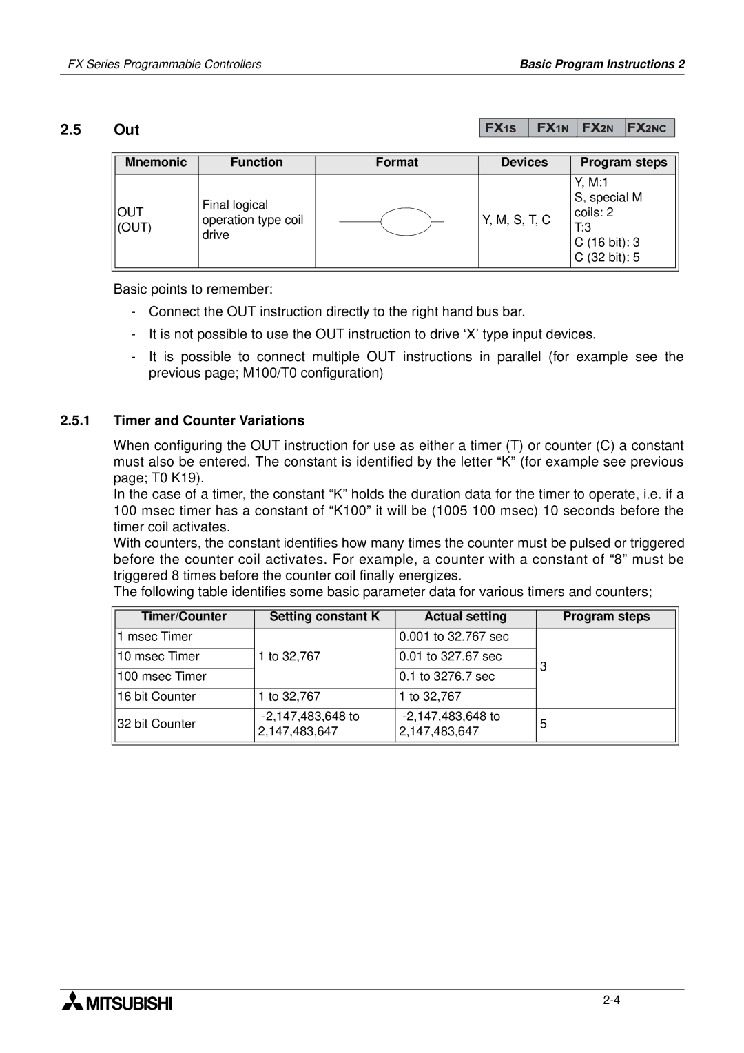
Mnemonic | Function | Format | Devices | Program steps |
|
|
|
| Y, M:1 |
| Final logical |
|
| S, special M |
OUT |
|
| coils: 2 | |
operation type coil |
| Y, M, S, T, C | ||
(OUT) |
| T:3 | ||
drive |
|
| ||
|
|
| C (16 bit): 3 | |
|
|
|
| |
|
|
|
| C (32 bit): 5 |
Basic points to remember:
-Connect the OUT instruction directly to the right hand bus bar.
-It is not possible to use the OUT instruction to drive ‘X’ type input devices.
-It is possible to connect multiple OUT instructions in parallel (for example see the previous page; M100/T0 configuration)
2.5.1Timer and Counter Variations
When configuring the OUT instruction for use as either a timer (T) or counter (C) a constant must also be entered. The constant is identified by the letter “K” (for example see previous page; T0 K19).
In the case of a timer, the constant “K” holds the duration data for the timer to operate, i.e. if a 100 msec timer has a constant of “K100” it will be (1005 100 msec) 10 seconds before the timer coil activates.
With counters, the constant identifies how many times the counter must be pulsed or triggered before the counter coil activates. For example, a counter with a constant of “8” must be triggered 8 times before the counter coil finally energizes.
The following table identifies some basic parameter data for various timers and counters;
| Timer/Counter | Setting constant K | Actual setting | Program steps |
|
| 1 msec Timer |
| 0.001 to 32.767 sec |
|
|
|
|
|
|
|
|
| 10 msec Timer | 1 to 32,767 | 0.01 to 327.67 sec | 3 |
|
|
|
|
|
| |
| 100 msec Timer |
| 0.1 to 3276.7 sec |
| |
|
|
|
| ||
|
|
|
|
|
|
| 16 bit Counter | 1 to 32,767 | 1 to 32,767 |
|
|
|
|
|
|
|
|
| 32 bit Counter | 5 |
| ||
| 2,147,483,647 | 2,147,483,647 |
| ||
|
|
|
| ||
|
|
|
|
|
|
|
|
|
|
|
|
