MonitorLink™ Connections
MonitorLink and MonitorLink Control
1.Connect a MonitorLink cable from the Mitsubishi Receiver/Controller back panel to the plasma monitor back panel.
2.Connect the L (left) and R (right) audio cables from the Mitsubishi Receiver/Controller to AUDIO LEFT and AUDIO RIGHT on the MonitorLink section of the plasma monitor back panel.
3.Connect the MonitorLink Control cable from the Mitsubishi Receiver/Controller back panel to the plasma monitor back panel.
Note:
1.Input TMDS signals conforming to DVI standards. The TMDS input corresponds to 1 link.
2.To maintain display quality, use a cable with a quality prescribedbyDVIstandardsthatiswithin5metersinlength.
External DVI Device with DVI-HDCP
1.Connect a DVI cable from the DVI output of the external DVI type device to the
2.Connect the L (left) and R (right) audio cables from the external DVI device to AUDIO LEFT and AUDIO RIGHT on the MonitorLink section of the plasma monitor back panel.
Note: When used as a DVI Input, MonitorLink input is compliant with HDCP and the
Pin Assignments and Signal Levels for 15 pin RGB (Analog) Connector
5 |
| 4 | 3 | 2 | 1 |
10 | 9 | 8 | 7 | 6 | |
15 | 14 | 13 | 12 | 11 | |
Pin No. | Signal (Analog) |
1 | Red |
2 | Green or |
3 | Blue |
4 | No connection |
5 | Ground |
6 | Red ground |
7 | Green ground |
8 | Blue ground |
9 | No connection |
10 | Sync signal ground |
11 | No connection |
12 | |
13 | Horizontal sync or Composite sync |
14 | Vertical sync |
15 | Data clock |
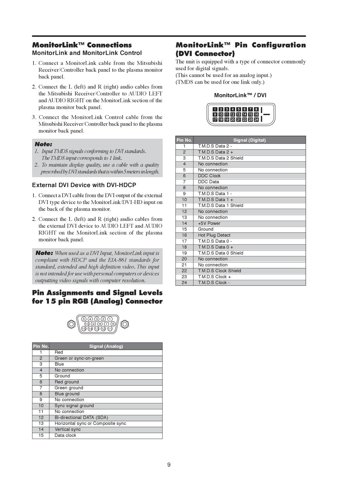
MonitorLink™ Pin Configuration (DVI Connector)
The unit is equipped with a type of connector commonly used for digital signals.
(This cannot be used for an analog input.) (TMDS can be used for one link only.)
MonitorLink™ / DVI
1 2 3 4 5 6 7 8
910 11 12 13 14 15 16
17 18 19 20 21 22 23 24
Pin No. | Signal (Digital) |
1T.M.D.S Data 2 -
2T.M.D.S Data 2 +
3T.M.D.S Data 2 Shield
4No connection
5No connection
6DDC Clock
7DDC Data
8No connection
9T.M.D.S Data 1 -
10T.M.D.S Data 1 +
11T.M.D.S Data 1 Shield
12No connection
13No connection
14+5V Power
15Ground
16Hot Plug Detect
17T.M.D.S Data 0 -
18T.M.D.S Data 0 +
19T.M.D.S Data 0 Shield
20No connection
21No connection
22T.M.D.S Clock Shield
23T.M.D.S Clock +
24T.M.D.S Clock -
9