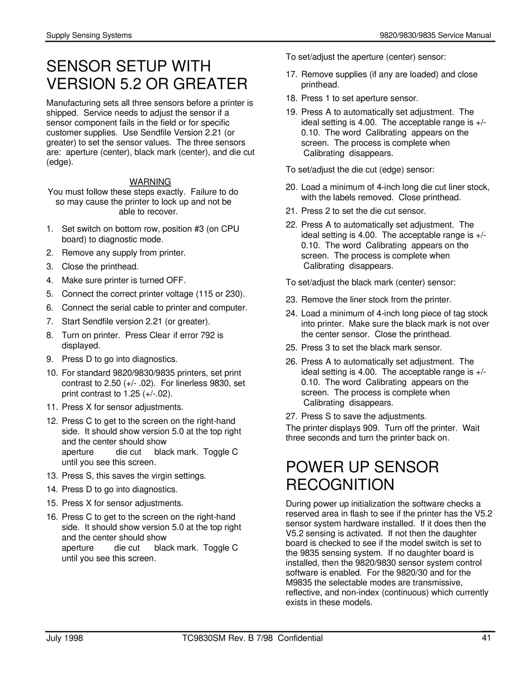
9835TM, 9820TM, 9830TM specifications
Monarch 9830TM, 9820TM, and 9835TM are part of a robust family of printers designed to meet the evolving demands of modern businesses. These printers are renowned for their efficiency, quality, and versatility in handling various print tasks.The Monarch 9830TM is particularly notable for its high-speed printing capabilities. It can deliver up to 600 dpi resolution, ensuring that images and text are sharp and vibrant. The printer is equipped with a user-friendly interface that supports seamless operation, making it accessible for users with varying technical expertise. Its compact design allows for easy integration into existing workflows, maximizing office space efficiency.
The Monarch 9820TM places a strong emphasis on durability. This model is built to withstand the rigors of heavy use, with a robust construction that ensures reliability over time. It features advanced thermal printing technology that not only enhances print quality but also reduces maintenance needs and operational costs. The 9820TM is particularly well-suited for environments that demand high-volume printing, such as retail and logistics.
On the other hand, the Monarch 9835TM introduces wireless connectivity capabilities, enabling mobile printing solutions. This model supports both Bluetooth and Wi-Fi connections, facilitating seamless communication with various devices. With the 9835TM, users can print directly from smartphones, tablets, or laptops, adding a layer of convenience that aligns with today’s mobile-centric work culture.
All three models utilize robust security features to protect sensitive data during printing tasks. They implement encryption protocols and access controls, ensuring that only authorized personnel can initiate print jobs. This focus on security is essential for businesses that deal with confidential information.
The Monarch series is also designed with energy efficiency in mind. These printers comply with eco-friendly standards, reducing power consumption without compromising performance. This commitment to sustainability makes them an appealing choice for organizations looking to lower their carbon footprint.
In conclusion, the Monarch 9830TM, 9820TM, and 9835TM stand out in the market for their combination of speed, durability, wireless capabilities, and security features. These printers cater to diverse business needs, from high-volume printing to mobile connectivity, ensuring they remain a reliable choice for professionals looking to enhance productivity.
