SECTION 1 | OVERVIEW |
|
|
Front of Router
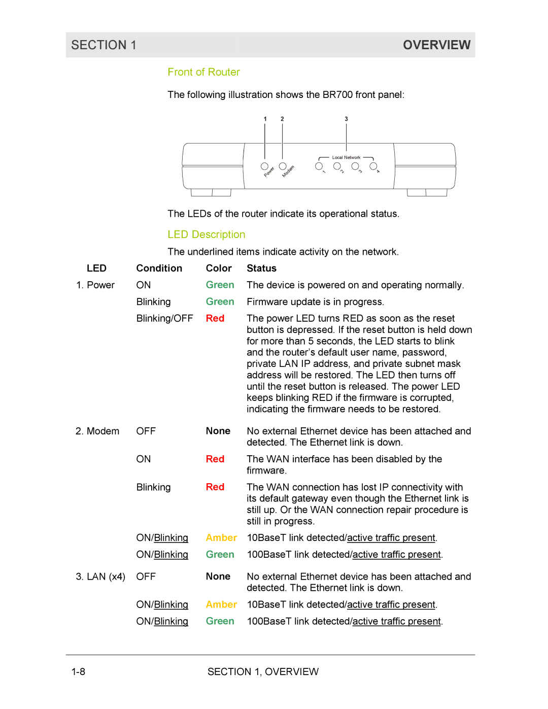
The following illustration shows the BR700 front panel:
1 | 2 | 3 |
|
| r |
|
| e |
| w | |
o |
| |
P |
|
|
|
|
| m |
|
| e | |
| d |
| |
o |
|
| |
M |
|
|
|
Local Network
1 | 2 | 3 | 4 |
The LEDs of the router indicate its operational status.
LED Description
| The underlined items indicate activity on the network. | ||
LED | Condition | Color | Status |
1. Power | ON | Green | The device is powered on and operating normally. |
| Blinking | Green | Firmware update is in progress. |
| Blinking/OFF | Red | The power LED turns RED as soon as the reset |
|
|
| button is depressed. If the reset button is held down |
|
|
| for more than 5 seconds, the LED starts to blink |
|
|
| and the router’s default user name, password, |
|
|
| private LAN IP address, and private subnet mask |
|
|
| address will be restored. The LED then turns off |
|
|
| until the reset button is released. The power LED |
|
|
| keeps blinking RED if the firmware is corrupted, |
|
|
| indicating the firmware needs to be restored. |
2. Modem | OFF | None | No external Ethernet device has been attached and |
|
|
| detected. The Ethernet link is down. |
| ON | Red | The WAN interface has been disabled by the |
|
|
| firmware. |
| Blinking | Red | The WAN connection has lost IP connectivity with |
|
|
| its default gateway even though the Ethernet link is |
|
|
| still up. Or the WAN connection repair procedure is |
|
|
| still in progress. |
| ON/Blinking | Amber | 10BaseT link detected/active traffic present. |
| ON/Blinking | Green | 100BaseT link detected/active traffic present. |
3. LAN (x4) | OFF | None | No external Ethernet device has been attached and |
|
|
| detected. The Ethernet link is down. |
| ON/Blinking | Amber | 10BaseT link detected/active traffic present. |
| ON/Blinking | Green | 100BaseT link detected/active traffic present. |
SECTION 1, OVERVIEW |
