replacing the microphone, leave the microphone in the boot.
4.Remove, if necessary, and replace the sound dampening pad.
5.As necessary, replace the speaker and/or microphone while out of the front cover housing.
NOTE: If the microphone is replaced, ensure that the microphone is reinstalled back into the rubber boot with the microphone port facing the round hole at the bottom of the boot.
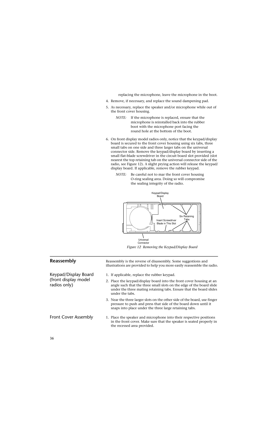
6.On front display model radios only, notice that the keypad/display board is secured to the front cover housing using six tabs, three small tabs on one side and three larger tabs on the universal connector side. Remove the keypad/display board by inserting a small
NOTE: Be careful not to mar the front cover housing
Keypad/Display
Board
Six Retaining
Insert Screwdriver
Blade in This Slot
Universal
Connector
Tabs
Figure 12 Removing the Keypad/Display Board
Reassembly
Keypad/Display Board (front display model radios only)
Front Cover Assembly
Reassembly is the reverse of disassembly. Some suggestions and illustrations are provided to help you more easily reassemble the radio.
1.If applicable, replace the rubber keypad.
2.Place the keypad/display board into the front cover housing at an angle such that the three small slots on the edge of the board slide under the three mating retaining tabs. Ensure that the board slides under the tabs.
3.Near the three larger slots on the other side of the board, use finger pressure to push and press that side of the board down until it snaps into place under the three large retaining tabs.
1.Place the speaker and microphone into their respective positions in the front cover. Make sure that the speaker is seated properly in the recessed area provided.
36
