HT 1000, JT 1000, MT 2000, MTS 2000, and MTX Series
Page
Safety
Foreword
Contents
Disassembly and Reassembly
Iii
Page
Replacement Parts Ordering
List of Tables
Vii
Related Publications Available Separately
Viii
Model Numbering System
Model Charts Model Programming Flashing, and Cloning
Conventional Systems Radios HT 1000 Models
Model Chart
H01RDH9PA3AN
Conventional Systems Radios JT 1000 and MT 2000 Models
PMUF6500D
Private Systems Radios MTS 2000 Models
A a
List of Batteries
List of Antennas
Xii
Xiii
Maintenance Specifications for VHF Radios
Xiv
Maintenance Specifications for 800MHz Radios
ALC
Glossary
Xvi
PLL
R N I N G
Introduction
Page
Recommended Test Equipment
Recommended Test Equipment
Field Programming
Service Aids and Recommended Tools
Motorola Part no Description Application
Service Aids
Recommended Service Tools
Service Tools
Test Mode
General Setup
Equipment Initial Control Settings
Earlier. If the radio is placed in Test Mode
NO. Description Function Beeps
Test Environments, HT 1000/JT 1000 Radios
Test Frequencies, HT 1000 / JT
Control Head Test Mode, HT 1000/JT 1000 Radios
Page
Page
Test Frequencies, MT 2000, MTS 2000, and MTX Series Radios
Test Environments, MT 2000, MTS 2000, and MTX Series Radios
Test Name Communications Radio Test SET Comments Analyzer
Receiver Performance Checks
Test Communications Radio Test SET Comments Name Analyzer
Transmitter Performance Checks
Power-up Display Codes
Error-Code Displays
Power-up Display Codes
Operational Display Codes
Operational Display Codes
General
Radio Alignment Procedure
Dtmf
Reference Oscillator Alignment
Perform the following procedures in the sequence indicated
Rated Audio
Front-End Pre-Selector VHF/UHF only
Standard Test Modulation 1 kHz Tone
Squelch
Transmitter Power
VHF UHF
Transmit Power Setting
Transmit Deviation Limit
Transmit Deviation Limit
Transmit Deviation Limit Reference
Transceiver Board Identification
Page
TX VCO Crossover Procedure
RX VCO Crossover Procedure
Signalling Deviation
Dtmf Tuning High Speed Signalling
MDC
Signalling Deviation
This Radio Contains STATIC-SENSITIVE
Disassembly and Reassembly
Removing the Battery
Disassembly to Board Level
Separating the Cover From the Chassis
Rotating the Front Cover
Separating Control Top From the Chassis
Removing the RF and Controller Boards
Disassembly of Control Top
Disassembly of Front Cover Assembly
Removing the Keypad/Display Board
Reassembly
Reinstalling the Speaker RetainerMAEPFBracket-22578-A
Page
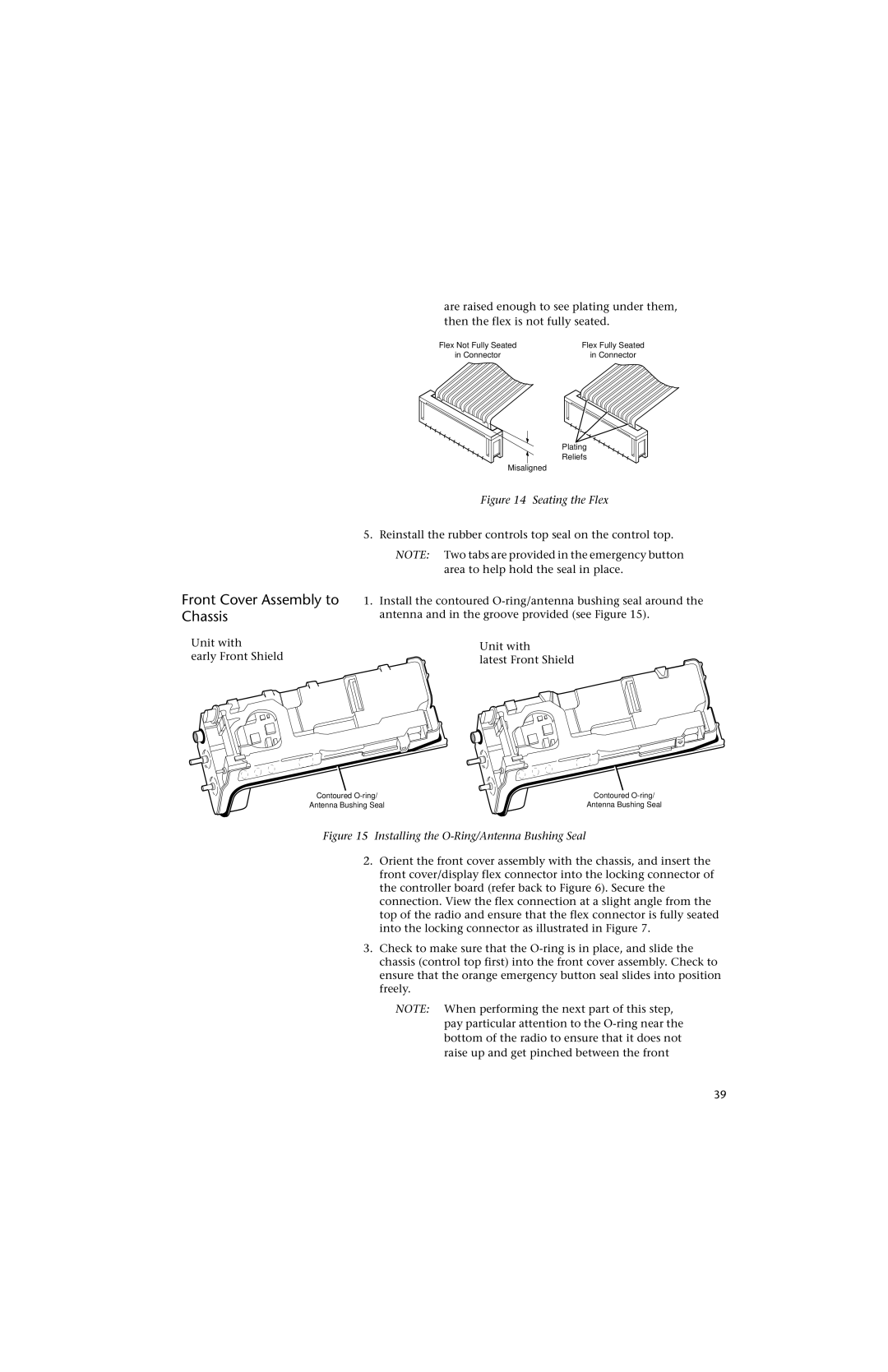
Seating the Flex
Front Cover Assembly to Chassis
Knobs, Antenna, and Battery
Preventive Maintenance
Maintenance
Inspection Cleaning
Introduction
General
Safe Handling of Cmos Devices
If neighboring Pbga components are heated
Specific
Above 365 degrees F degrees C., they will
Suffer die-bond delamination and possible
Solder Tabs
Page
U t i o n
To Replace an Pbga compo- nent
Thin Small Outline Package Tsop Components
Shields
Removing and Replacing
To Replace the RF PA
To Remove the RF PA
Page
Exploded Views
Refer to electrical parts list transceiver board
Top-Display Radios
Keypad Radios
SHIELD, PA
Uni-board Radios
Page
Circuit Board Layers
Transceiver Controller Schematic and Circuit Board Notes
SYN
Integrated Circuit Details with Pin-Out Names
35U50 X Wlyww
Wlyww
Universal Connector Option Select OPT SEL Definition
Universal Connector Pin Numbers and Signal Assignments
MAEPF-2
Unless stated
CAPACITOR, Fixed pF ± 5%
Diode See Note
Fuse 1-Amp
U102
NC NC NC NC CLK
Error Feedback
5VREG SB+
BATT+
MAEPF-2630
Transistor See Note
CAPACITOR, Fixed pF ±30%
RESISTOR, Fixed Ω ± 5%
0625W unless stated
Connector EXT. ANT
Switch
These Levels Measured by Removing R52
DAC CLK
DET VDD VDD2
NC NC NC NC NC CLK
Cext
Batt
MAEPF-2630
50V unless stated
CAPACITOR, Fixed pF ± 25%
COIL, RF nH
CR6 CR7 CR8 CR9
RF Switch
ABP GND1 GND2 GND3 AG2
GND1 GND2 GND3 GND4 GND5
DET
VDD VDD2
NC3 NC4 NC5 NC6 NC7 NC8 NC9
VMULT2 Frefout
MAEPF-26305
RESISTOR, Fixed Ω ± 0.0625W
3Pack.xls CAPACITOR, Fixed pF ± 5% Sheet Unless stated
U105 U104
VCO MOD RAW B+
5VREG LCK
LCK SW B+
SYN SEL
Transceiver Board Parts List and Component Location Diagrams
Fuse 1.0A Filter See Note 2, 73.35MHZ
CAPACITOR, Fixed pF ±5%
RESISTOR, FixedΩ ± 5% .0625W unless stated
DIODE, Zener See Note 1
U101
GND32
CLK Batt
GND31
GND30
NUF6499B/C and NUF6502B/C 900MHz
Diode
U105
GND30 REF OSC
SYN SYN SEL
GND27
GND21
NUF/PMUF6499D 900MHz
Electrical Parts List, Transceiver 900MHz NUF/PMUF6499D
ANODE2 Pacntl INT CAP Antswbs Switch
Reset 5V TX 0V RX
GND GND1 GND2 RF Switch
To Universal Connector
Synthesizer
Je di HT/JT Tra ns .
DIODE, Zener
U701
HearClear Option
Hear
Clear
U702
Resetb
U708
Asficsel
Intmic Optenable Spkrcom
SB+ Intspkr Error
Spkrcom Aupaen Extspkr
Volsense NC3 Extspkrsel
U706
U709
NC5 NC6 NC7 NC8
Controller BOARD’ Parts List and Component Location Diagram
RESISTOR, Fixed Ω ± 5%
GND10 GND11 GND12 GND13 Gnda
Chact Reset
Upclk A3 Clke VDD3 VDD4
GND VEE
Vccence Enoe Enwe
Busy
Analog Section SCK
Power Section
SPI TX Data Mosi
SPI RX Data Miso
Vdd Regulator
Main Power Switch
Vaud Regulator
U712
MAEPF-25672
CAPACITOR, Fixed pF ±
103
DIODE, Zener See Note
Sqdet Chact Univio Pwrrst Sqdet Chact
Hiclmpen Compen Lcdis Hcidis Ffen
Icenab Ffout
Cpnenab Expout Ffenab Cbufou
VSS4 VSS1 Synsel Roscsel Ascficsel Bootstrp Csgen
UV2CS Bootstrp
Scirx Eecs Muxcntl SEL LED
Uvcs
OPTB+/BOOTSEL Mosi
SWB+ GND1 Blcntl Intspkr Reset Spkrcom Intmic
GND2 Keyint OPTSEL1
Extspkr Datalatch Extmic
NTN7512D/E, NTN7513E, NTN7857D/E and NTN7858D/E 107
MAEPF-26096
HearClear Components Not Placed on NCN6176A
109
CAPACITOR, Fixed pF ± 5% 50V unless stated
RESISTOR, Fixed Ω ± 0.0625W unless stated
Expin Lodsab Cbufin Expbyp Rssiin
SWB+ Sqdet Chact
Ffin VAG Nfilin
Ffcnt L
U705
Digital Section
U702
Main Power Switch Vdd Regulator
Front Cover Display Flex
Motorola Online
Replacement Parts Ordering
Mail Orders
115
FAX Orders
Telephone Orders
Parts Identification
116
Introduction Circuit Description
Appendix a
Appendix a
Appendix . Secure Module
Signal Name Connector Plug Function P1 PIN Number
Troubleshooting Secure Operations
Appendix a . Key Variable Loader
Service Aid Retrofit Instructions
General
Anti-static precautions must be observed at all times
Set Secure-Equipped Field
Set XL IC Present Field
Enable Secure On Desired
Secure Alignment Procedure
Secure Retrofit Tuning
Channels
Appendix a . Secure Deviation
Compensation
Removal
Removal And Installation
Appendix . Secure Module Location Detail
XL&XL
Appendix a . RSS Secure Parameters
Appendix B . HT 1000 Models
Appendix B
Appendix B
H01RDC9AA1BN
Appendix B . JT 1000 Models
Appendix B . MT 2000 Models
PMUE7272B PMCN6147B
H01SDH9AA7AN
Appendix B . MTS 2000 Models
H01RDD9PW1AN
H01RDH9PW1AN
H01SDH9PW1AN
H01UCH6PW1AN
PMUF6499D Pmcn
Appendix B . MTX Series Models
H01KDF9DB5AN
H01RDD9DB4AN
H01RDH9DB7AN
H01SDH9DB7AN
H01UCC6DF3AN
H01WCC4DB3AN
H01WCH4DB7AN
Page
Motorola, Inc West Sunrise Boulevard Ft. Lauderdale, FL