IDEN Digital Multi-Service, Data-Capable Portable
I580
Manual Revisions
Safety and General Information
Electro Magnetic Interference Compatibility
Medical Devices
Accessory Safety Information
Cleaning and Drying Considerations
Safety and General Information
Model Information
Model Numbering System
Model Specifications
General Receiver Transmitter
Contents
Chapter Basic Level Test Modes and Procedures
Chapter Field Level Test Modes and Procedures
Appendix a Ordering Replacement Parts and Kits
Preface
Who Should Use This Manual
How This Manual Is Organized
Conventions Used in This Manual
Related Publications
Overview
IDEN Digital Modulation Technology
Spectrum of iDEN Quad 16QAM
IDEN Voice Compression Technology
RF Transmission Bursts
Calling Area Coverage
Bluetooth Wireless System
Global Positioning System GPS Section
MOTOtalk
SIM Cards
Removing and Inserting a SIM Card
To remove a SIM card Figure
Removing a SIM Card
To insert a SIM card Figure
FEATURES, ICONS, and Indicators
I580 Features
Display Icons
Main Menu Icons
Status Icons
Power-Up Sequence
DISPLAYS, MESSAGES, and Alerts
Power-Down Sequence
Self-Test Errors
Self-Test Reset Errors
Messages
Service Messages
Service Messages
Alert Tones
Alert Tones
Alert Tones
Alert Tones
Using the Optional Vibrate Function
Vibrator Settings
To set unit to vibrate for all calls
From the main menu, select Settings 2-Way Radio Alert Type
Preparing for Basic Level Testing
Reference Accessories
Test Equipment
Reference Unit
Reset Condition
Basic Level Checks and Self Tests
Customer Care
Test Conditions
Basic-Level Test Checklist
Preventive Maintenance
Basic-Level Test Checklist
To clean the unit takes approximately 3 minutes
Mechanical and Electrical Checks
SIM Card Swap Test
Shock and Pressure test time is approximately 3 minutes
SIM Card Swap test time is approximately 5 minutes
Accessory Swap Test
Accessory Swap test time is approximately 5 minutes
Lockup Test
Lockup Test time is approximately 6 minutes
Battery Connections Test
Testing the GPS Receiver
Battery Connections test time is approximately 5 minutes
To test the GPS Receiver
Self-Test Procedures
Voltage Recognition Test
Voltage Recognition test time is approximately 4 minutes
Programming Menu Settings Check
Passcode Test
Passcode test time is approximately 5 minutes
From the main menu, select Settings Display/Info Contrast
Phone Calls Features
Way Radio Options
Volume Features
Security Features
Personalize
From the main menu, select Settings Security GPS PIN
Advanced Features
Call Performance Test
Call Performance test time is approximately 7 minutes
Basic Level Test Modes and Procedures
Entering Debug Mode
To enter Debug/Trace Mode
Test Modes
Trace Mode Display Screens
Display Screens
GPS
Test Mode Test Procedures
Entering Test Mode
To enter Test Mode
Audio Loopback Test
ESN and Imei Matching Test
Debug Check
Audio Loopback test time is approximately 3 minutes
ESN/IMEI Matching test time is approximately 6 minutes
To monitor the data in the unit
68P80401P05
Technician Test Procedures
Connecting the Unit to the RSS Workstation
Programming the i580 Unit
Codeplug Troubleshooting
To access the codeplug Help topic in Windows
Codeplug Help
Preparing for Field Level Testing
Preparing Equipment for Testing
Using RSS
Connecting an iDEN Unit to the R-2660
Typical R-2660 Setup
To connect the unit to the R-2660
To enter Initial Registration mode
Operating the R-2660
RF Zone Fields and Values
Disassembly Sequence Flowchart
Assembly/Disassembly Procedures
Disassembling and Reassembling the Unit
Remove Battery Cover
Install
Remove
Remove Battery
Remove SIM Card
Remove Antenna
Preparing for Field Level Testing Remove Antenna
Remove Back Housing
Remove Main Board, Keypad
Remove Flip Assembly
Procedure to remove flip assembly
Preparing for Field Level Testing Remove Flip Assembly
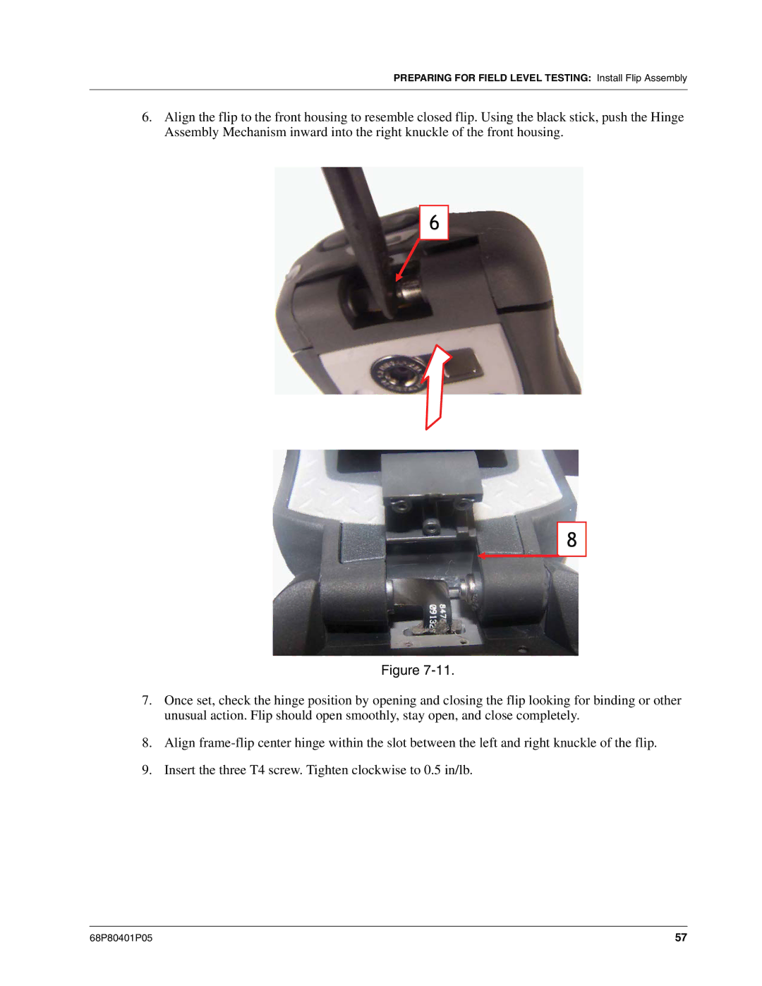
Install Flip Assembly
Procedure to install flip assembly
Preparing for Field Level Testing Install Flip Assembly
Exploded View and Parts List
I580 Component Parts List
I580 Exploded View
Field Level Test Modes and Procedures
Field-Level Test Checklist
Required Test Equipment
Field-Level Test Checklist
Done Technical Tests Pass Fail
See the Strong Signal Environment section
Registration/Call Test
Signal Quality Error SQE Test
R-2660
TX Power Test
See Entering Test Mode Press Menu, Edit
Bit Error Rate BER Test
Pass
Power-Up Test
Keypad Test
Audio Test
Use this test to check the audio portion of the unit
Reset Test
Reset
Reset Log Test
To perform the reset log test
Model Assembly MA Test Mode Test
GPS Global Positioning System Receiver Test
Use this test on a unit to check its GPS functionality
Yes
Bluetooth Test
This Page intentionally left blank
Mechanical Parts Rework and Repair
Recommended Equipment
Recommended Tools
Recommended Supplies
Rework/Repair Requirements
Board Preparation
Components Identification
Mechanical Parts Rework Procedure
Removal Procedure
Land Preparation Procedure
Installation Procedure
4 J600 RF Connector
6 J401 30 Pin Board-to-Flex Connector
5 J752 Audio Jack
7 J400 80 Pin Board-to Flex Connector
8 M002 Simm Connector
9 M105 Battery Contact
SW-all Key/Switch
10 M2 2 Pin-Contact
11 J753 Microphone Socket
13 D401 through D412 LED
Ordering Replacement Parts and Kits
Customer Service
Replacement Parts
Domestic Orders
Replacement Kits
Table A-1
Mid Rate Travel Chargers
Bluetooth Accessories
NNTN2344 NA
Recommended Test Equipment and Tools
Recommended Programming Equipment
Table A-2. Recommended Test Equipment and Tools
Table A-3. Recommended Programming Equipment
Table A-4. Recommended Software
TTY
@68P80401P05@