Hardware Installation
RS-422/485 Interface Settings
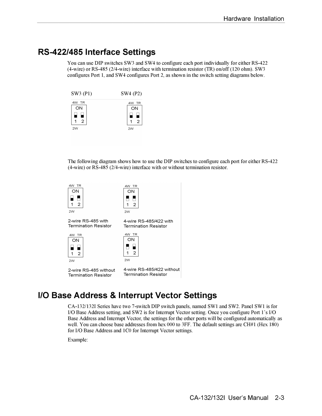
You can use DIP switches SW3 and SW4 to configure each port individually for either RS-422 (4-wire) or RS-485 (2/4-wire) interface with termination resistor (TR) on/off (120 ohm). SW3 configures Port 1, and SW4 configures Port 2, as shown in the switch setting diagrams below.
The following diagram shows how to use the DIP switches to configure each port for either RS-422 (4-wire) or RS-485 (2/4-wire) interface with or without termination resistor.
I/O Base Address & Interrupt Vector Settings
CA-132/132I Series have two 7-switch DIP switch panels, named SW1 and SW2. Panel SW1 is for I/O Base Address setting, and SW2 is for Interrupt Vector setting. Once you configure Port 1’s I/O Base Address and Interrupt Vector, the settings for the other ports will be configured automatically as well. You can choose base addresses from hex 000 to 3FF. The default settings are CH#1 (Hex 180) for I/O Base Address and 1C0 for Interrupt Vector settings.
Example:
CA-132/132I User’s Manual 2-3