When you wish to configure your Port 1’s I/O base address to 180, the DIP switch settings of panel SW1 should be as follows:
A3 | A4 | A5 | A6 | A7 | A8 | A9 | Hex |
|
|
|
|
|
|
|
|
On | On | On | On | Off | Off | On | 0 × 180 |
|
|
|
|
|
|
|
|
When you wish to configure your Port 1’s INT Vector to 1C0, the DIP switch settings of panel SW2 should be as follows:
A3 | A4 | A5 | A6 | A7 | A8 | A9 | Hex |
|
|
|
|
|
|
|
|
On | On | On | Off | Off | Off | On | 0 × 1C0 |
|
|
|
|
|
|
|
|
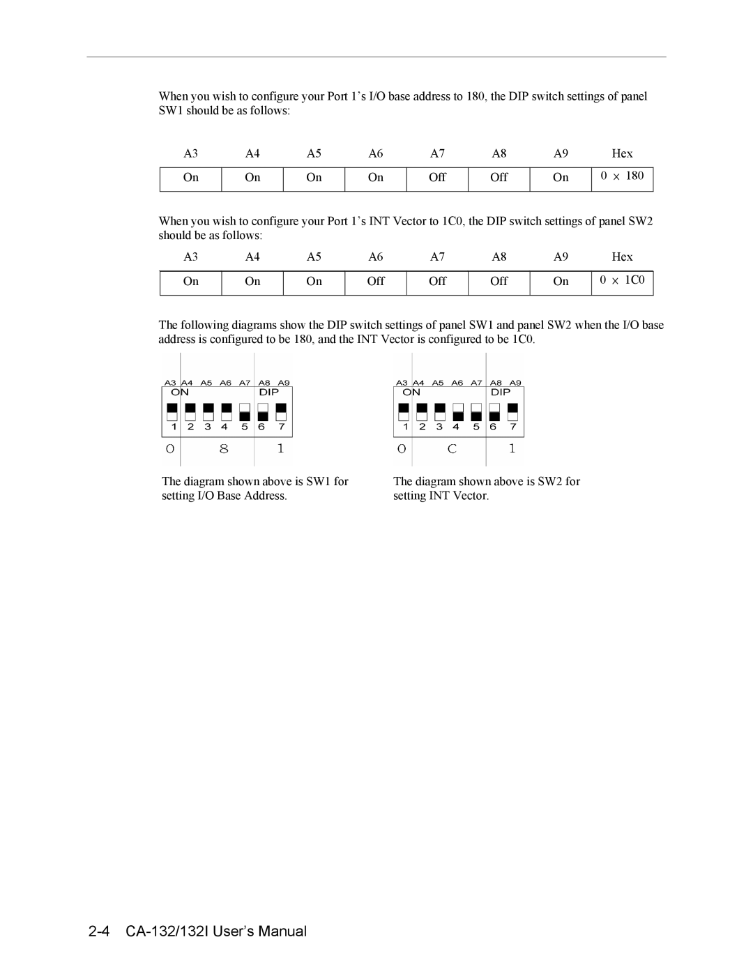
The following diagrams show the DIP switch settings of panel SW1 and panel SW2 when the I/O base address is configured to be 180, and the INT Vector is configured to be 1C0.
The diagram shown above is SW1 for setting I/O Base Address.
The diagram shown above is SW2 for setting INT Vector.