First Edition, July
Moxa EtherDevice Switch EDS-726 Series User’s Manual
Trademarks
Copyright Notice
Disclaimer
Table of Contents
Chapter EDS Configurator GUI
Introduction
Industrial Networking Capability
Package Checklist
Features
Overview
Recommended Software and Accessories
Useful Utility and Remote Configuration
Getting Started
Connection Caution
RS-232 Console Configuration 115200, None, 8, 1, VT100
EDS-726 Series User’s Manual
Key Function
Configuration by Telnet Console
Configuration by Web Browser
EDS-726 Series User’s Manual
Disabling Telnet and Browser Access
Featured Functions
System Identification
Configuring Basic Settings
Switch Description
Password
Switch Name
Switch Location
Account
Password
Allowable Hosts Input format
Accessible IP
Any host on a specific subnetwork can access the EDS-726
Any host can access the EDS-726
Name
Enable
Port
Description
Port Type
Network
Port Transmission Speed
FDX Flow Control
Default Gateway
Auto IP Configuration
Switch IP Address
Switch Subnet Mask
System Up Time
Time
Current Time
Current Date
System File Update-By Remote Tftp
System File Update-By Local Import/Export
System File Update-By CF Card
Using Port Trunking
Factory Default
Port Trunking Concept
Configuring Port Trunking
Member Ports/Available Ports
Setting Description
Trunk Group Maximum of 4 trunk groups
Trunk Type
Snmp
Configuring Snmp
V1, V2c Write/Read Community
Snmp Read/Write Settings
Snmp Versions
V1, V2c Read Community
Trap Server IP/Name
Trap Settings
Gigabit Ethernet Redundant Ring Capability 300 ms
Using Communication Redundancy
Switch Object ID
Private MIB information
Turbo Ring Concept
Initial Setup
When the number of EDS-726 units in the Turbo Ring is even
Ring Coupling
Configuring Turbo Ring
STP/RSTP Concept
What is STP?
STP Requirements
How STP Works
Port Speed Path Cost 802.1D Edition 802.1w-2001
STP Calculation
STP Configuration
STP Reconfiguration
Differences between Rstp and STP
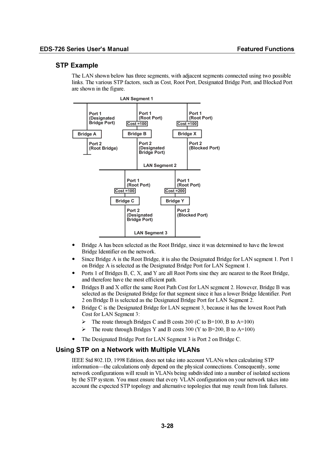
STP Example
Using STP on a Network with Multiple VLANs
Configuring STP/RSTP
Bridge priority
Forwarding Delay
Root/Not Root
Protocol of Redundancy
Port Cost
Configuration Limits of RSTP/STP
Enable STP per Port
Port Priority
How Traffic Prioritization Works
Using Traffic Prioritization
What is Traffic Prioritization?
Traffic Prioritization Concept
Ieee 802.1p Priority Level Ieee 802.1D Traffic Type
Differentiated Services DiffServ Traffic Marking
Traffic Prioritization
QoS Classification
Configuring Traffic Prioritization
Traffic Queues
Inspect COS
Default Port Priority
Queuing Mechanism
Inspect TOS
CoS Mapping
Setting Description Factory
TOS/DiffServ Mapping
What is a VLAN?
Using Virtual LAN
Virtual LAN Vlan Concept
Communication Between VLANs
VLANs and Moxa EtherDevice Switch
Benefits of VLANs
Managing a Vlan
HUB
Sample Applications of VLANs using Moxa EDS-726
Vlan Port Settings
Configuring 802.1Q Vlan
Port Forbidden Vlan List
Management Vlan ID
Port Pvid
Port Fixed Vlan List Tagged
Benefits of Multicast
Using Multicast Filtering
What is an IP Multicast?
Concept of Multicast Filtering
Network without multicast filtering
Multicast Filtering
Igmp Multicast Filtering
Multicast Filtering and Moxa EtherDevice Switch
Igmp Internet Group Management Protocol Snooping Mode
Query Mode
Enabling Multicast Filtering
Configuring Igmp Snooping
Igmp Snooping Settings
Static Multicast MAC
Igmp Table
Igmp Snooping
Static Multicast Router Port
Querier
Join Port
Add Static Multicast MAC
Add New Static Multicast Address to the List
None
Port Mode Setting Description Factory Default
Configuring Gmrp
Port Setting Description Factory Default
Gmrp enable Setting Description Factory Default
Broadcast Storm Protection
Using Bandwidth Management
Configuring Bandwidth Management
Gmrp Table
Static Port Lock
Using Port Access Control
Traffic Rate Limiting Settings
Ieee
Message Exchange
802.1X
Configuring Ieee
Shared Key
Database Option
Radius Server
Server Port
Local User Database Setup
802.1X Re-Authentication
802.1X Re-Authentication
Static Port Lock
Local User Database Setup
802.1X Table
Configuring Email Warning
Using Auto Warning
Email Alarm Events Settings
Port Event
MoxaEtherDeviceSwitch0001@SwitchLocation
Event Types
System Event
Email Settings
Activate your settings
Configuring Relay Warning
Relay Alarm Events Settings
Configuring Relay Event Types
Override relay alarm settings
Relay Alarm List
Enable Line-Swap-Fast-Recovery
Using Line-Swap-Fast-Recovery
Using Set Device IP
Configuring Line-Swap Fast Recovery
Set up the connected devices
Configuring Set Device IP
Bi-directional
Using Diagnosis
Mirror Port
Output data stream
Monitor by Switch
Using Monitor
Ping
Monitor by Port
Using the MAC Address Table
ALL
Using Event Log
EDS Configurator GUI
Broadcast Search
Starting EDS Configurator
Search by IP address
Upgrade Firmware
Modify IP Address
Export Configuration
Import Configuration
Unlock Server
EDS-726 Series User’s Manual
MIB II.5 Icmp Group
MIB II.1 System Group
MIB II.2 Interfaces Group
MIB II.4 IP Group
MIB II.11 Snmp Group
MIB II.10 Transmission Group
MIB II.17 dot1dBridge Group
Private Traps
Public Traps
Interface
Modular Managed Switch System, EDS-72610G
Gigabit Ethernet Interface Module, IM series
Power
Mechanical
Optical Fiber
Fast Ethernet Interface Module, IM series
Interface
Regulatory Approvals
Environmental
Service Information
Following services are provided
Moxa Internet Services
Serial Number
Problem Report Form
Product Return Procedure