Back Panel
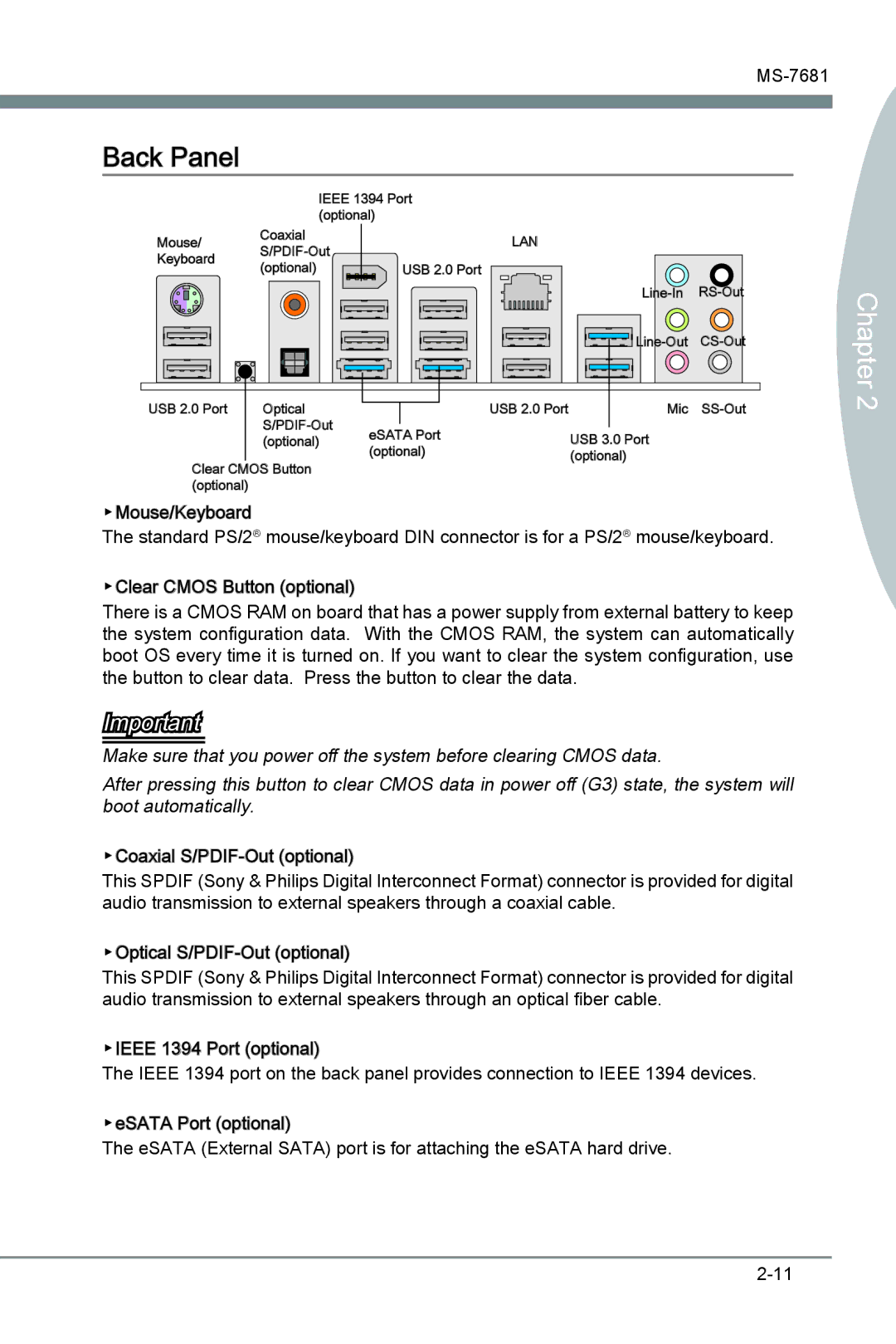
IEEE 1394 Port (optional)
Mouse/ | Coaxial | LAN |
|
| |||
Keyboard |
|
| |
(optional) | USB 2.0 Port |
| |
|
| ||
|
| ||
|
| ||
USB 2.0 Port | Optical |
| USB 2.0 Port | Mic |
| eSATA Port |
| USB 3.0 Port | |
| (optional) |
| ||
Clear CMOS Button | (optional) |
| (optional) | |
|
|
| ||
(optional) |
|
|
|
|
▶Mouse/Keyboard
The standard PS/2® mouse/keyboard DIN connector is for a PS/2® mouse/keyboard.
▶Clear CMOS Button (optional)
There is a CMOS RAM on board that has a power supply from external battery to keep the system configuration data. With the CMOS RAM, the system can automatically boot OS every time it is turned on. If you want to clear the system configuration, use the button to clear data. Press the button to clear the data.
Important
Make sure that you power off the system before clearing CMOS data.
After pressing this button to clear CMOS data in power off (G3) state, the system will boot automatically.
▶Coaxial![]()
![]()
![]()
![]() -Out
-Out
This SPDIF (Sony & Philips Digital Interconnect Format) connector is provided for digital audio transmission to external speakers through a coaxial cable.
▶Optical![]()
![]()
![]()
![]() -Out
-Out
This SPDIF (Sony & Philips Digital Interconnect Format) connector is provided for digital audio transmission to external speakers through an optical fiber cable.
▶IEEE![]()
![]() 1394 Port (optional)
1394 Port (optional)
The IEEE 1394 port on the back panel provides connection to IEEE 1394 devices.
▶eSATA Port (optional)
The eSATA (External SATA) port is for attaching the eSATA hard drive.