Chapter 4 - Hardware removal/ Replacement
Chapter 4 - Hardware removal/Replacement
This chapter’s procedures describe removal and replacement of the main hardware components of the CommPlete 4000. Before removing or replacing any component, disconnect the cables from the back of the CommPlete 4000 and remove the CommPlete 4000 from its rack enclosure per instructions. The CommPlete 4000 has been designed to make this process as efficient as possible, but if you experience problems, contact
Disconnecting Cables and Removal from Enclosure
The steps below describe how to remove the CommPlete 4000 from its rack enclosure. These steps must be followed before any internal component can be removed or replaced.
Warning: Anytime power is removed, turn off the Master Power switch inside the front door.
Note: In order to make
1Remove the power cord from the back of the CommPlete 4000.
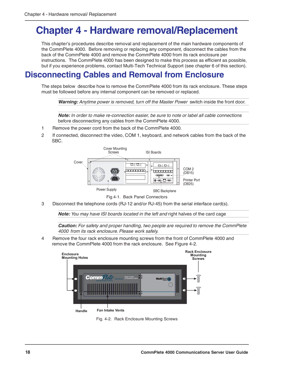
2If connected, disconnect the video, COM 1, keyboard, and network cables from the back of the SBC.
Cover Mounting |
|
Screws | ISI Boards |
Cover
MODEM Line | MODEM Line | MODEM Line | MODEM Line |
120
Power Supply | SBC Backplane |
|
Fig.4-1. Back Panel Connectors
COM 2 (DB15)
Printer Port (DB25)
3Disconnect the telephone cords
Caution: For safety and proper handling, two people are required to remove the CommPlete 4000 from its rack enclosure. Please work safely.
4Remove the four rack enclosure mounting screws from the front of CommPlete 4000 and remove the CommPlete 4000 from the rack enclosure. See Figure
Enclosure | Rack Enclosure |
Mounting | |
Mounting Holes | Screws |
Single Processor |
Communications Server |
Handle | Fan Intake Vents |
Fig. 4-2. Rack Enclosure Mounting Screws
18 | CommPlete 4000 Communications Server User Guide |