Chapter 2 - Installing Your CommPlete 4000
If the ISI4608PCI or ISI4608UPCI is used, connections between it and external modems are made via the supplied octopus cable going between the
If the
The SBC board has cable connectors for adding a monitor, a keyboard, and a mouse or other serial device (on COM1), and network connection. Cable connectors and boards are shown in Figure
Cover Mounting |
|
Screws | ISI Boards |
Cover | MODEM Line |
| MODEM Line |
| MODEM Line |
| MODEM Line |
120
Power Supply | SBC Backplane |
|
Figure 2-1. Back Panel Connectors
SBC Board Cabling
COM 2 (DB15)
Printer Port (DB25)
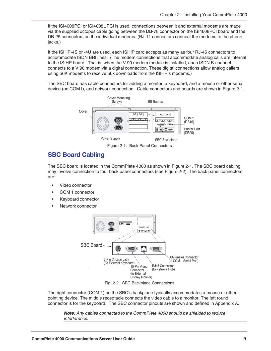
The SBC board is located in the CommPlete 4000 as shown in Figure
•Video connector
•COM 1 connector
•Keyboard connector
•Network connector
SBC Board |
| |
DB9 (male) Connector | ||
(to COM 1 Serial Port) | ||
(To External Keyboard) | ||
RJ45 Connector | ||
Connector | (to Network Hub) | |
(to External |
| |
Display Monitor) |
|
Fig. 2-2. SBC Backplane Connections
The right connector (COM 1) on the SBC’s backplane typically accommodates a mouse or other pointing device. The middle receptacle connects the video cable to a monitor. The left round connector is for the keyboard. The SBC connector pinouts are shown and defined in Appendix A.
Note: Any cables connected to the CommPlete 4000 should be shielded to reduce interference.
CommPlete 4000 Communications Server User Guide | 9 |