Appendices
Carrier Card | Expansion Card |
Communication Module
X
Power Supply Unit or other source of
excessive voltage | X |
Y
Y
Example Diagram Showing Creepage
and Clearance Distances
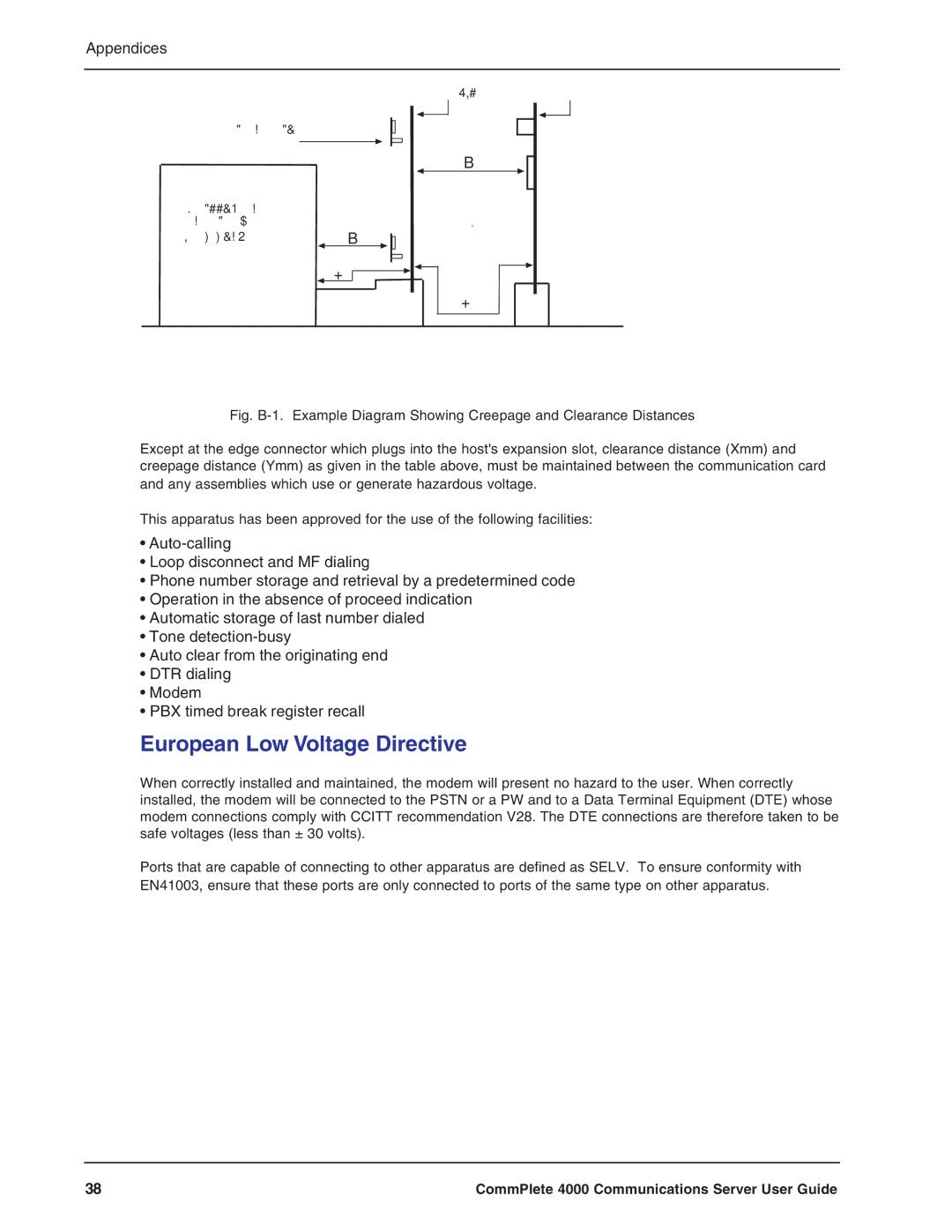
Fig. B-1. Example Diagram Showing Creepage and Clearance Distances
Except at the edge connector which plugs into the host's expansion slot, clearance distance (Xmm) and creepage distance (Ymm) as given in the table above, must be maintained between the communication card and any assemblies which use or generate hazardous voltage.
This apparatus has been approved for the use of the following facilities:
•
•Loop disconnect and MF dialing
•Phone number storage and retrieval by a predetermined code
•Operation in the absence of proceed indication
•Automatic storage of last number dialed
•Tone
•Auto clear from the originating end
•DTR dialing
•Modem
•PBX timed break register recall
European Low Voltage Directive
When correctly installed and maintained, the modem will present no hazard to the user. When correctly installed, the modem will be connected to the PSTN or a PW and to a Data Terminal Equipment (DTE) whose modem connections comply with CCITT recommendation V28. The DTE connections are therefore taken to be safe voltages (less than ± 30 volts).
Ports that are capable of connecting to other apparatus are defined as SELV. To ensure conformity with EN41003, ensure that these ports are only connected to ports of the same type on other apparatus.
38 | CommPlete 4000 Communications Server User Guide |