Chapter 4 - Hardware removal/ Replacement
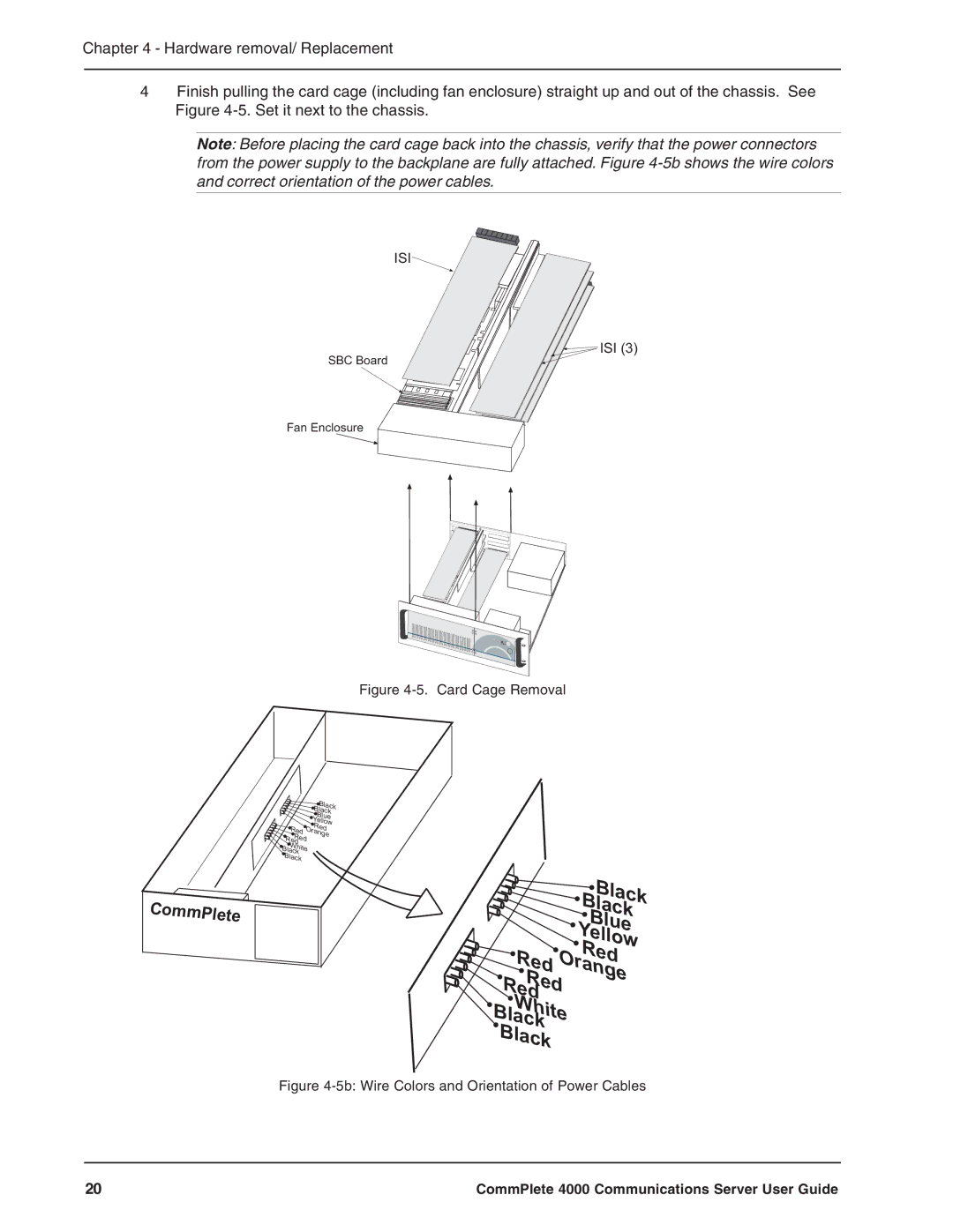
4Finish pulling the card cage (including fan enclosure) straight up and out of the chassis. See Figure
Note: Before placing the card cage back into the chassis, verify that the power connectors from the power supply to the backplane are fully attached. Figure
ISI
SBC Board
Fan Enclosure
![]() ISI (3)
ISI (3)
Figure 4-5. Card Cage Removal
|
|
| Black |
|
|
| Black |
|
|
| Blue |
|
|
| Yellow |
| Red O | Red | |
R Red | range | ||
| ed |
|
|
B | W |
|
|
hite |
|
| |
| lack |
|
|
Black |
|
| |
CommPlete
Black
Black
Blue
Yellow
Red
Red Orange
RedRed
White
Black
Black
Figure 4-5b: Wire Colors and Orientation of Power Cables
20 | CommPlete 4000 Communications Server User Guide |