Structural Concrete Pump
Heres HOW to GET Help
Mayco ST-45HRM CE Concrete Pump
ST-45 Pump Specifications
ST-45HRM CE Concrete PUMP- Engine Specifications
ST-45HRM CE Concrete Pump Dimensions
ST-45HRM CE Concrete PUMP- Dimensions
EC Declaration of Conformity
Guaranteed Sound Power Level
Seriously injured if you do not follow directions
ST-45HRM CE Concrete PUMP- Safety Message Alert Symbols
Instructions Always wear approved eye and hearing protection
Always wear approved respiratory protection
General Safety
ST-45HRM CE Concrete PUMP- Rules for Safe Operation
Never operate the pump in an explosive
ST-45HRM CE Concrete Pump Rules for Safe Operation
Maintenance Safety
Transporting
Towing
Emergencies
Battery
Machine Safety Decals
ST-45HRM CE Concrete PUMP- Operation and Safety Decals
ST-45HRM CE Concrete PUMP- Operation and Safety Decals
ST-45HRM CE Concrete PUMP- Operation and Safety Decals
ST-45HRM CE Concrete PUMP- Important Hand Signals
Concrete Mix Design
ST-45HRM CE Concrete PUMP- General Information
ST-45HRM CE Concrete PUMP- General Information
Regional Differences
Use a minimum
Pumping Cycle
ST-45HRM CE Concrete PUMP- HOW IT Works
Major Pump Components
ST-45HRM CE Concrete PUMP- Pump Components
ST-45HRM CE Concrete PUMP- Pump Components
ST-45HRM CE Concrete PUMP- Control BOX Components
Initial Servicing
ST-45HRM CE Concrete PUMP- Engine Components
Operating Suggestions
ST-45HRM CE Concrete PUMP- Operating Procedures
Getting the concrete to flow through
Notremotely
Pumping Tips
Admixtures
Priming the Pump and Delivery System with Slurry
Reverse Pumping Procedure
Shuttle Tube Inspection Procedure
Clearing Concrete Blockage
Chip the concrete out of the reducer with the pry bar
Carefully knock the end of the hose away from the reducer
Nience
ST-45HRM CE Concrete PUMP- Inspection
Fuel Check
Before Starting
Hydraulic Oil
Engine OIL Check
Rear Stabilizer Stand
Pump, set the rear stabilizers as follows
Locate both the left and right rear stabilizer stands
Emergency Stop Switch
ST-45HRM CE Concrete PUMP- Initial START-UP Procedure
Ignition Switch
If any of the status indicator lights
Strokes within 1 minute
Control Switch
Running
Engine Speed
Cooling FAN
Pressure Test
Optional Radio Remote Control
Cylinder Lubrication BOX
Important Notice! During freezing
Tires/Wheels/Lug Nuts
ST-45HRM CE Concrete PUMP-TRAILER Safety Guidelines
TiresWear/Inflation
Lug Nut Torque Requirements
Wheel Lug Nuts Tightening Sequence
Running Gear Manufacturers
ST-45HRM CE Concrete Pump -TOWING Information
Towing Level
ST-45HRM CE Concrete PUMP-TOWING Information
It is legal to use safety chains up
ST-45HRM CE Concrete PUMP-TOWING Information
Visual Inspection
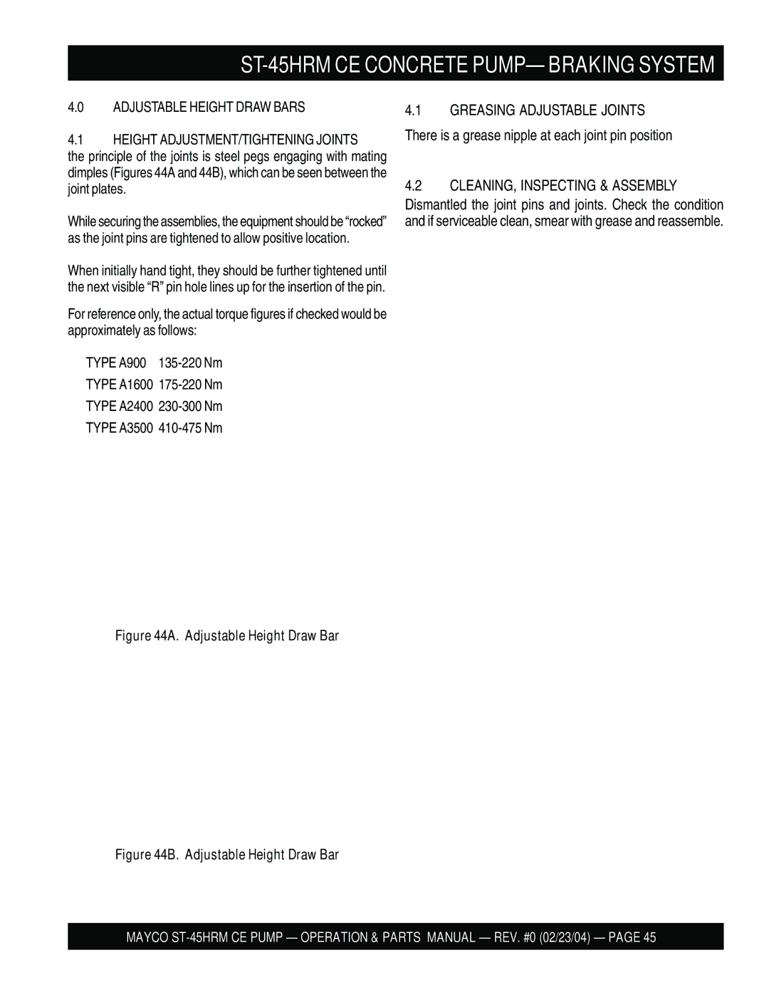
ST-45HRM CE Concrete PUMP- Braking System
It is now possible to begin the setup procedure
Braking System
Brakes
Coupling Andtransmission System
ST-45HRM CE Concrete Pump Braking System
Couplings with Handbrake Mounted on Draw BAR Figures 41F-41J
Adjuster
CLEANING, Inspecting & Assembly
Greasing Adjustable Joints
Bearings
Inspection
Meredith & Eyre Couplings do not require for
Meredith & Eyre Coupling with Bellows and Shaft Nipples
ST-45HRM CE Concrete PUMP- Braking System
Brake lining contaminated with grease
Failure of bond between brake lining
Application Fastern Size Lbf.ft
Torque Figures by Application
Cleaningthe Pump and Delivery System
ST-45HRM CE Concrete PUMP- Maintenance Pump
ST-45HRM CE Concrete PUMP- Maintenance Pump
Hydraulic OIL System Maintenance
Engine Hatz Model 3M41 57 HP Diesel
Battery Maintenance
Brake System
Lubricant made for hitch balls
To set maximum pump pressure
ST45 Pressure Setting Sequence
Cleaningthe Lubrication BOX
ST45 Accumulator Circuit
Checking Accumulator Bladder Pressure
Pilot Relief Valve Cartridge Adjustment
Cylinder CUP Replacement Procedure
Oil prior to installation
Size and type of aggregate Type of concrete being pumped
Wear Plate Installation
Wear Plate and Ring Replacement Procedure
Install the two cylinder O rings Hopper Interior Assy, Item
Wear Ring installation
Emergency Stop Switch Functionaltest
Proximity Switch Functionaltest
Extended Storage Instructions
Hydrauilc Hose Connections
ST-45HRM CE Concrete PUMP- Hydraulic Hose Connections
ST-45HRM CE Concrete PUMP- Hydraulic Hose Connections
ST-45HRM CE Concrete PUMP- Hydraulic Hose Connections
ST-45HRM CE Manifold Port Locations
Page
Appendix ST-45HRM CE Concrete Pumpconcrete MIX
Appendix ST-45HRM CE Concrete Pump Concrete MIX
Slump Test 1/3 Full
Appendix ST-45HRM CE Concrete Pump Slump Test
Engine Troubleshooting
ST-45HRM CE Concrete Pump Troubleshooting Engine
Hydraulic System Troubleshooting
ST-45HRM CE Concrete PUMP-TROUBLESHOOTING Hydraulic
Electrical System Troubleshooting
ST-45HRM CE Concrete PUMP-TROUBLESHOOTING Electrical
Shotcrete System
Shotcrete System
Recommended Shotcrete System
13 EM23808D Nozzle ASSEMBLY, 2 H-D
COUPLING, 3 H-D CF
10 EM23101 AIR Vibrator Assy TBD
Recommended Shotcrete Accessories
Air passages clean
Material has Passedthroughthe Entire Hose Length
AIR Hose
AIR Vibrator
Bushing
Valve
Items Found In the Items Number Column
ST-45HRM CE PUMP- Explanation of Code in Remarks Column
Part numbers on this Suggested
ST-45HRM CE Suggested Spare Parts
Decal Placement
DECAL, Volume Control TBD DECAL, Shuttle Tube Danger
DECAL, Maintenance
DECAL, ST-45
DECAL, Lubrication BOX
Safety Grids Assy
WASHER, Lock 1/4 MED
GRID, Blade Shaft 4.5 X
WASHER, Flat 1/4
Grid Support Bracket
HUB and Drum Assy
Brake
Stub Axle
OIL Seal
Inner Bearing Cone
Brake Components Assy
Adjuster Shoe Post
Readjustable Wedge
Half Shell
Eyelet
Towing Coupler Assy
Energy Store
Brake Lever Assy
BREAK-AWAY Cable TBD Body Assy
Bellows
Hopper Assy
ST-45HRM CE Concrete PUMP- Hopper Assy
SHAFT, Adaptor
REMIXER, Shaft
CAP Screw
WASHER, Lock 3/8
ST-45HRM CE Concrete PUMP- Hopper Attachment Assy
Tanque Transmission Hatz 57HP Assy
Hopper Attachment Assy
Hinge PIN
Splash Plate
Splash Plate PIN
NUT, HEX 1 NC
Hopper Interior Assy
Shuttle Axle Ring Seal
Swing Axle Bushing
Wear RING, Hard Faced
RING, Insert Steel
Shuttle Cylinder Assy
Shuttle CRANK, Splined Shaft
Thrust Washer
Tensioner
NUT Flex Lock
Fuel and Hydraulic Tank Connections Assy
ST-45HRM CE Concrete PUMP- Fuel and Hydraulictank Assy
Fuel and Hydraulic Tank Assy
Rear Hood Assy
Suction Nipple 3/4
ELBOW, Suction
Plug 3/4 Pipe SQ H
Adapter 1/2- FF- S
Front Cover Assy
Front Cover ASSY.ST-45HRM CE Concrete PUMP- Front Cover Assy
WASHER, Lock 1/4 Diameter
Document BOX
NUT Lock Nyloc 1/4
Heat Exchanger Assy
WASHER, Flat 3/8
GUARD, Heat Exchanger
Heat Exchanger
WASHER, Flat 5/16
Engine and Frame Assy
Connector
Connector LINK, Chain
WASHER, Lock
Shock Mount
Throttle and Water Filter Assy
ST-45HRM CE Concrete PUMP-THROTTLE and Water Filter Assy
Bracket
Safety Link Assembly
Clevis Yoke 1/4
KIT, Solenoid W/BRACKET
Hydraulic Pump Assy
Bolt 12 MM X 1 Allen Head
COUPLING, Engine
COUPLING, Chain
COUPLING, Pump
Lubrication Pistons Assy
ST-45HRM CE Concrete PUMP- Lubrication Pistons Assy
Cable Proximity Switch
Switch Proximity
Lubrication BOX
Plug
Electrical System Assy
Sistema Electrico Hatz Assy
Terminal Connector
Connector Boot
Pump Wire
CABLE, Proximity Switch
Accumulator Assy
BRACKET, Accumulator
Accumulator 1 Gallon
Hhcs 3/8 Diameter
Accumulator Repair KIT
ST-45HRM CE Concrete PUMP- Manifold Assy
ADAPTOR, Elbow
Test Port
Adapter
CARTRIDGE, Pilot Relief
Remixer Control Assy
NUT, HEX 5/16 DIAMETER- NC
Valve Remix W/LEVER
TEE, Custom
Adapter Gauge
Battery Assy
Battery HOLD-DOWN Strap
Battery BOX
Battery
CABLE, Battery Negative
ST-45HRM CE Concrete PUMP- Lubrication Panel
Grease Points
41 in .04 m
Connectoir
HOSE, Plastic
HOSE, Plastic TBD HOSE, Steel
Control BOX Interior Door Assy
ST-45HRM CE Concrete PUMP- CONTRL. BOX Interior Door Assy
Relay , Small
SWITCH, Emergency Cycle TBD NUT Connector
RELAY, Large
SOLENOID, 12 Volt
Control BOX Mounting Assy
ST-45HRM CE Concrete PUMP- Control BOX Mounting Assy
492366 Screw HHC 5/16-18x1-1/2 EM510703
Control BOX Assy
Ignition Switch W/ KEY
Emergency Stop Switch
Directional Control Switch
Pump Control Switch
ST-45HRM CE Concrete PUMP- Control BOX Door Wiring
ST-45HRM CE Concrete PUMP- Control BOX Interiorwiring
ST-45HRM CE Concrete PUMP-TERMINAL Blockwiring Diagram
Page
ST-45HRM CE Concrete PUMP- Control BOX ELECT. Diagram
Sheet 2
TB1
Description Quantity
ST-45HRM CE- Hydraulic Diagram
ST-45HRM CE- Optional Radio Control
ST-45HRM CE-TAIL Lightswiring Diagram
Freightpolicy
Terms and Conditions of Sale Parts
Hydraulic Drive Models
Mechanical Drive Models
Heres HOW to GET Help