HPC167064 Interrupts (Continued)
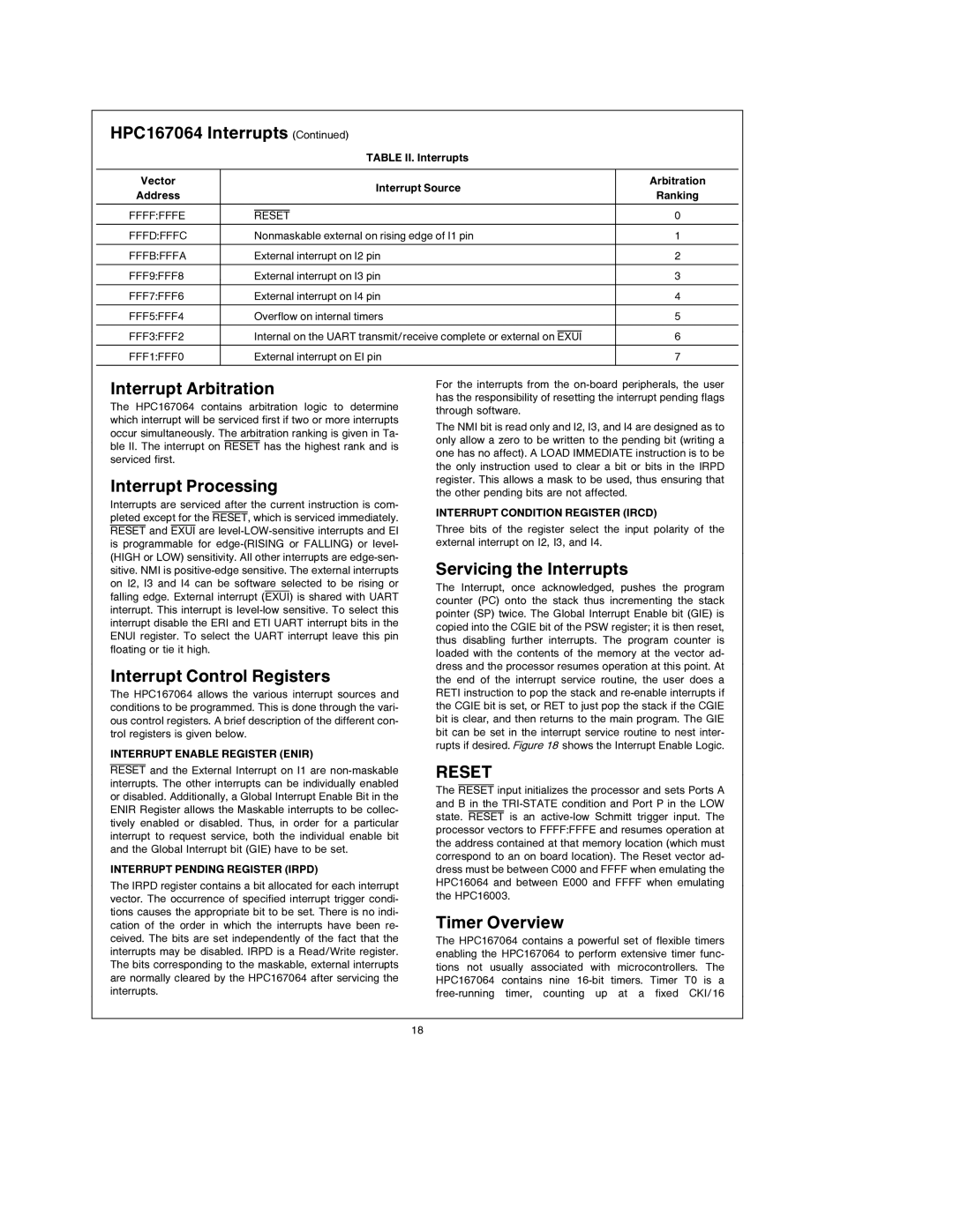
TABLE II. Interrupts
Vector |
|
| Interrupt Source | Arbitration | ||
Address |
|
| Ranking | |||
|
|
|
|
| ||
|
|
|
|
|
|
|
|
|
|
|
|
|
|
FFFF:FFFE |
| RESET | 0 | |||
|
|
|
|
|
| |
FFFD:FFFC |
| Nonmaskable external on rising edge of I1 pin | 1 | |||
|
|
|
|
|
| |
FFFB:FFFA |
| External interrupt on I2 pin | 2 | |||
|
|
|
|
|
| |
FFF9:FFF8 |
| External interrupt on I3 pin | 3 | |||
|
|
|
|
|
| |
FFF7:FFF6 |
| External interrupt on I4 pin | 4 | |||
|
|
|
|
|
| |
FFF5:FFF4 |
| Overflow on internal timers | 5 | |||
|
|
|
|
|
| |
|
|
|
|
|
| |
FFF3:FFF2 |
| Internal on the UART transmit/receive complete or external on EXUI | 6 | |||
|
|
|
| |||
FFF1:FFF0 |
| External interrupt on EI pin | 7 | |||
|
|
|
|
|
|
|
Interrupt Arbitration
The HPC167064 contains arbitration logic to determine which interrupt will be serviced first if two or more interrupts occur simultaneously. The arbitration ranking is given in Ta- ble II. The interrupt on RESET has the highest rank and is serviced first.
Interrupt Processing
Interrupts are serviced after the current instruction is com- pleted except for the RESET, which is serviced immediately. RESET and EXUI are
Interrupt Control Registers
The HPC167064 allows the various interrupt sources and conditions to be programmed. This is done through the vari- ous control registers. A brief description of the different con- trol registers is given below.
INTERRUPT ENABLE REGISTER (ENIR)
RESET and the External Interrupt on I1 are
INTERRUPT PENDING REGISTER (IRPD)
The IRPD register contains a bit allocated for each interrupt vector. The occurrence of specified interrupt trigger condi- tions causes the appropriate bit to be set. There is no indi- cation of the order in which the interrupts have been re- ceived. The bits are set independently of the fact that the interrupts may be disabled. IRPD is a Read/Write register. The bits corresponding to the maskable, external interrupts are normally cleared by the HPC167064 after servicing the interrupts.
For the interrupts from the
The NMI bit is read only and I2, I3, and I4 are designed as to only allow a zero to be written to the pending bit (writing a one has no affect). A LOAD IMMEDIATE instruction is to be the only instruction used to clear a bit or bits in the IRPD register. This allows a mask to be used, thus ensuring that the other pending bits are not affected.
INTERRUPT CONDITION REGISTER (IRCD)
Three bits of the register select the input polarity of the external interrupt on I2, I3, and I4.
Servicing the Interrupts
The Interrupt, once acknowledged, pushes the program counter (PC) onto the stack thus incrementing the stack pointer (SP) twice. The Global Interrupt Enable bit (GIE) is copied into the CGIE bit of the PSW register; it is then reset, thus disabling further interrupts. The program counter is loaded with the contents of the memory at the vector ad- dress and the processor resumes operation at this point. At the end of the interrupt service routine, the user does a RETI instruction to pop the stack and
RESET
The RESET input initializes the processor and sets Ports A and B in the
Timer Overview
The HPC167064 contains a powerful set of flexible timers enabling the HPC167064 to perform extensive timer func- tions not usually associated with microcontrollers. The HPC167064 contains nine
18