Connection Diagram
TL/DD/11046 – 17
Top View
Order Number HPC167064, EL
See NS Package Number EL68C
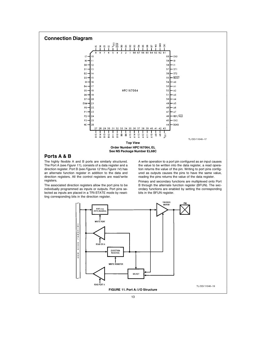
Ports A & B
The highly flexible A and B ports are similarly structured. The Port A (see Figure 11 ), consists of a data register and a direction register. Port B (see Figures 12 thru Figure 14 ) has an alternate function register in addition to the data and direction registers. All the control registers are read/write registers.
The associated direction registers allow the port pins to be individually programmed as inputs or outputs. Port pins se- lected as inputs are placed in a
A write operation to a port pin configured as an input causes the value to be written into the data register, a read opera- tion returns the value of the pin. Writing to port pins config- ured as outputs causes the pins to have the same value, reading the pins returns the value of the data register.
Primary and secondary functions are multiplexed onto Port B through the alternate function register (BFUN). The sec- ondary functions are enabled by setting the corresponding bits in the BFUN register.
TL/DD/11046 – 19
FIGURE 11. Port A: I/O Structure
13