Operating Modes
To offer the user a variety of I/O and expanded memory options, the HPC167064 has four operating modes. The various modes of operation are determined by the state of both the EXM pin and the EA bit in the PSW register. The state of the EXM pin determines whether on-chip EPROM will be accessed or external memory will be accessed within the address range of the on-chip EPROM. The on-chip EPROM range of the HPC167064 is C000 to FFFF (16 kbytes).
A logic ‘‘0’’ state on the EXM pin will cause the HPC device to address on-chip EPROM when the Program Counter (PC) contains addresses within the on-chip EPROM address range. A logic ‘‘1’’ state on the EXM pin will cause the HPC device to address memory that is external to the HPC when the PC contains on-chip EPROM addresses. The function of the EA bit is to determine the legal addressing range of the HPC device. A logic ‘‘0’’ state in the EA bit of the PSW register does two things—addresses are limited to the on- chip EPROM range and on-chip RAM and Register range, and the ‘‘illegal address detection’’ feature of the WATCH-
DOG logic is engaged. A logic ‘‘1’’ in the EA bit enables accesses to be made anywhere within the 64 kbytes ad- dress range and the ‘‘illegal address detection’’ feature of the WATCHDOG logic is disabled.
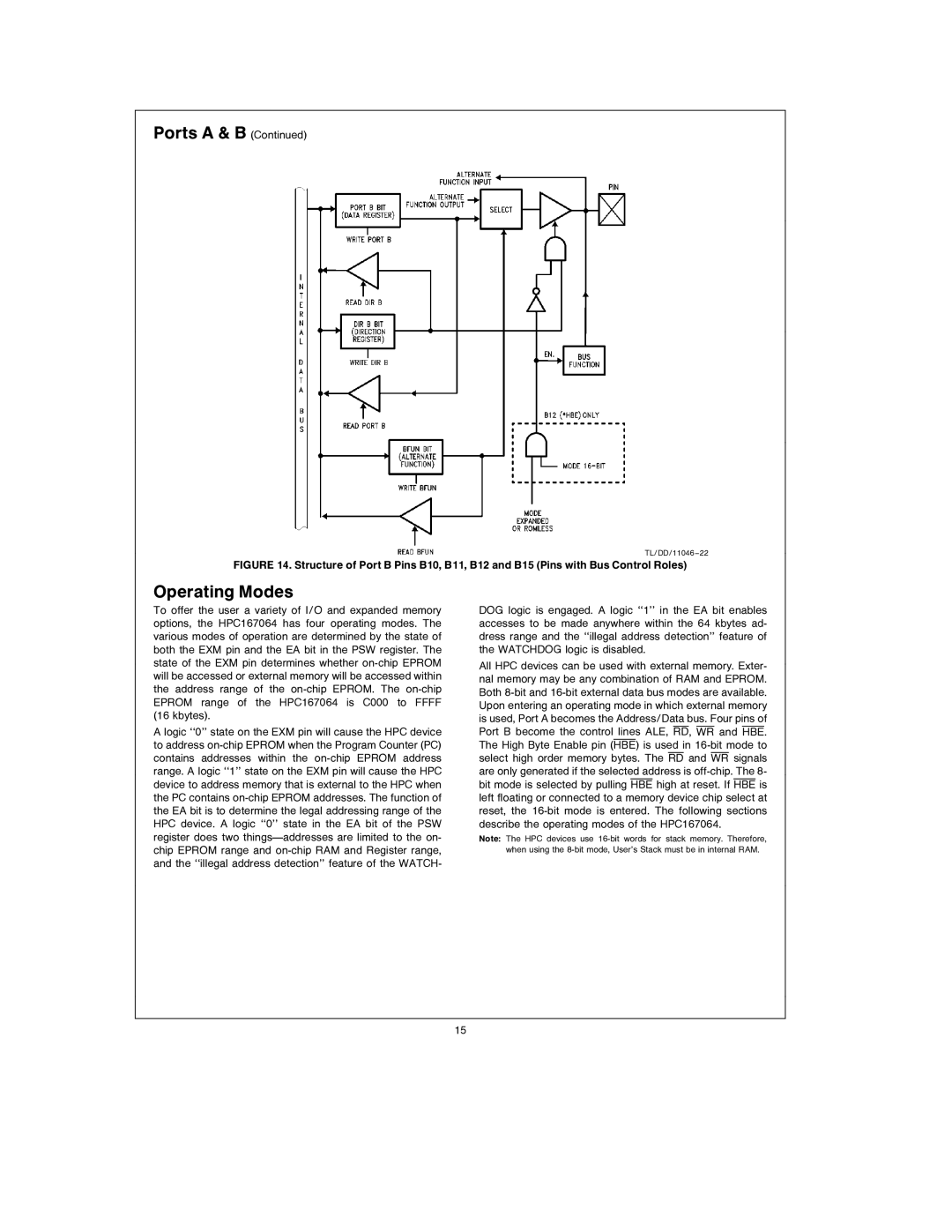
All HPC devices can be used with external memory. Exter- nal memory may be any combination of RAM and EPROM. Both 8-bit and 16-bit external data bus modes are available. Upon entering an operating mode in which external memory is used, Port A becomes the Address/Data bus. Four pins of Port B become the control lines ALE, RD, WR and HBE. The High Byte Enable pin (HBE) is used in 16-bit mode to select high order memory bytes. The RD and WR signals are only generated if the selected address is off-chip. The 8- bit mode is selected by pulling HBE high at reset. If HBE is left floating or connected to a memory device chip select at reset, the 16-bit mode is entered. The following sections describe the operating modes of the HPC167064.
Note: The HPC devices use 16-bit words for stack memory. Therefore, when using the 8-bit mode, User’s Stack must be in internal RAM.