HPC167064 Operating Modes
SINGLE CHIP NORMAL MODE
In this mode, the HPC167064 functions as a
EXPANDED NORMAL MODE
The Expanded Normal mode of operation enables the HPC167064 to address external memory in addition to the
TABLE I. HPC167064 Operating Modes
Operating Mode | EXM | EA | Memory | |
Pin | Bit | Configuration | ||
| ||||
|
|
|
| |
0 | 0 | C000 – FFFF | ||
|
|
|
| |
Expanded Normal | 0 | 1 | C000 – FFFF | |
| 0300 – BFFF | |||
|
|
| ||
|
|
|
| |
1 | 0 | C000 – FFFF | ||
|
|
|
| |
Expanded ROMless | 1 | 1 | 0300 – FFFF | |
|
|
|
|
In this mode, the
EXPANDED ROM MODE
This mode of operation is similar to
Wait States
The internal EPROM can be accessed at the maximum op- erating frequency with one wait state. With 0 wait states, internal ROM accesses are limited to )/3 fC max. The HPC167064 provides four software selectable Wait States that allow access to slower memories. The Wait States are selected by the state of two bits in the PSW register. Addi- tionally, the RDY input may be used to extend the instruc- tion cycle, allowing the user to interface with slow memories and peripherals.
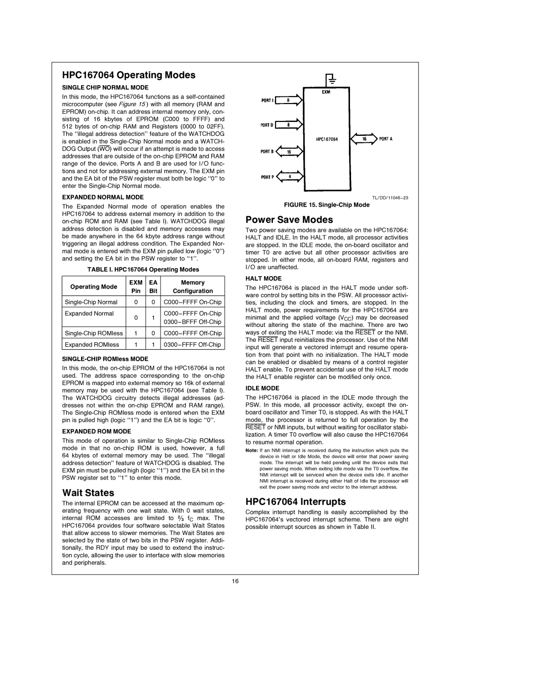
TL/DD/11046 – 23
FIGURE 15. Single-Chip Mode
Power Save Modes
Two power saving modes are available on the HPC167064: HALT and IDLE. In the HALT mode, all processor activities are stopped. In the IDLE mode, the
HALT MODE
The HPC167064 is placed in the HALT mode under soft- ware control by setting bits in the PSW. All processor activi- ties, including the clock and timers, are stopped. In the HALT mode, power requirements for the HPC167064 are minimal and the applied voltage (VCC) may be decreased without altering the state of the machine. There are two ways of exiting the HALT mode: via the RESET or the NMI. The RESET input reinitializes the processor. Use of the NMI input will generate a vectored interrupt and resume opera- tion from that point with no initialization. The HALT mode can be enabled or disabled by means of a control register HALT enable. To prevent accidental use of the HALT mode the HALT enable register can be modified only once.
IDLE MODE
The HPC167064 is placed in the IDLE mode through the PSW. In this mode, all processor activity, except the on- board oscillator and Timer T0, is stopped. As with the HALT mode, the processor is returned to full operation by the RESET or NMI inputs, but without waiting for oscillator stabi- lization. A timer T0 overflow will also cause the HPC167064 to resume normal operation.
Note: If an NMI interrupt is received during the instruction which puts the device in Halt or Idle Mode, the device will enter that power saving mode. The interrupt will be held pending until the device exits that power saving mode. When exiting Idle mode via the T0 overflow, the NMI interrupt will be serviced when the device exits Idle. If another NMI interrupt is received during either Halt of Idle the processor will exit the power saving mode and vector to the interrupt address.
HPC167064 Interrupts
Complex interrupt handling is easily accomplished by the HPC167064’s vectored interrupt scheme. There are eight possible interrupt sources as shown in Table II.
16