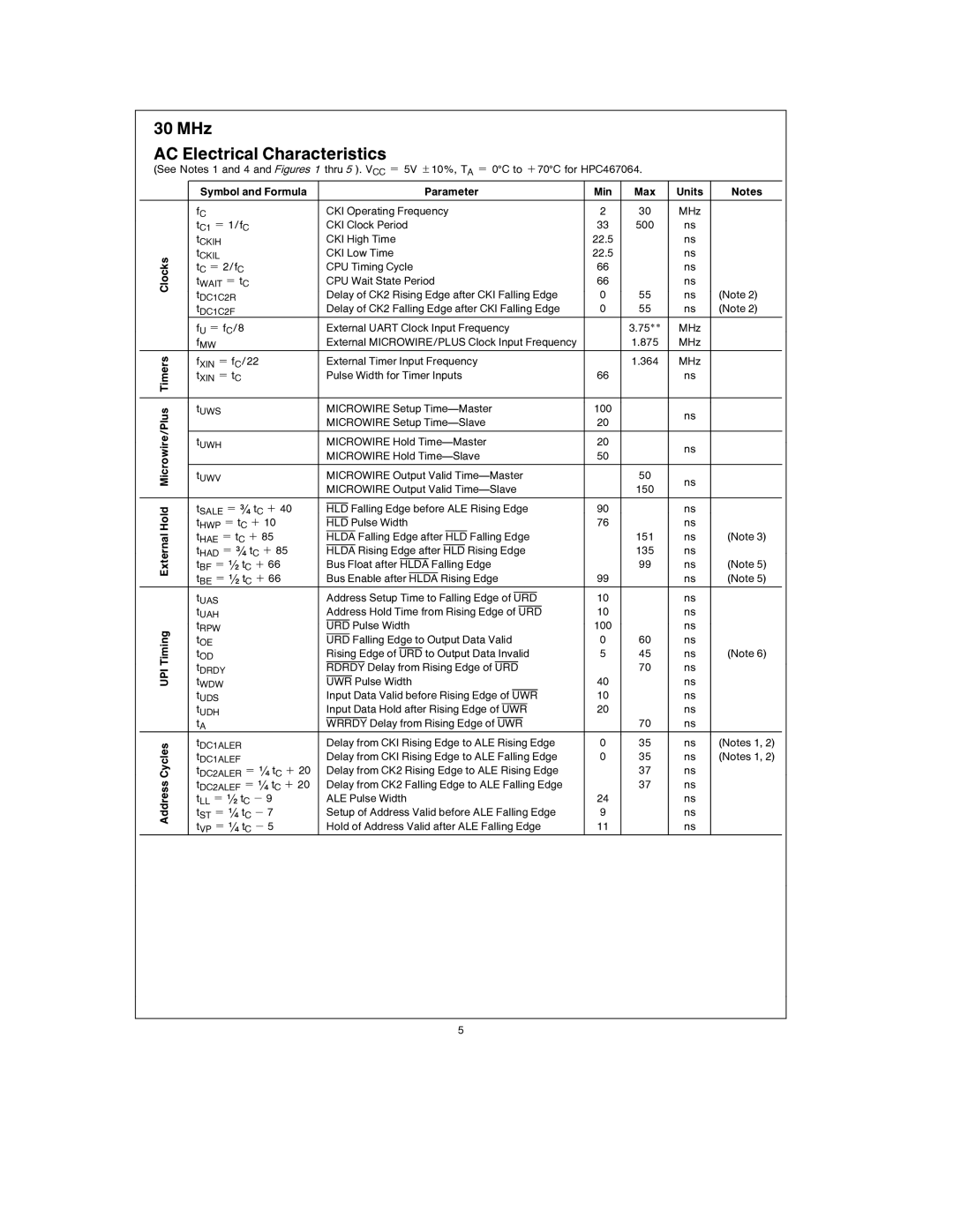
30 MHz
AC Electrical Characteristics
(See Notes 1 and 4 and Figures 1 thru 5 ). VCC e 5V g10%, TA e 0§C to a70§C for HPC467064.
| Symbol and Formula |
|
|
|
|
|
|
|
| Parameter | Min | Max | Units | Notes | ||||||||||
|
|
|
|
|
|
|
|
|
|
|
|
|
|
|
|
|
|
|
|
|
|
|
|
|
| fC |
| CKI Operating Frequency | 2 | 30 | MHz |
| |||||||||||||||||
| tC1 e 1/fC |
| CKI Clock Period | 33 | 500 | ns |
| |||||||||||||||||
| tCKIH |
| CKI High Time | 22.5 |
| ns |
| |||||||||||||||||
Clocks | tCKIL |
| CKI Low Time | 22.5 |
| ns |
| |||||||||||||||||
tC e 2/fC |
| CPU Timing Cycle | 66 |
| ns |
| ||||||||||||||||||
|
|
|
| |||||||||||||||||||||
| tWAIT e tC |
| CPU Wait State Period | 66 |
| ns |
| |||||||||||||||||
| tDC1C2R |
| Delay of CK2 Rising Edge after CKI Falling Edge | 0 | 55 | ns | (Note 2) | |||||||||||||||||
| tDC1C2F |
| Delay of CK2 Falling Edge after CKI Falling Edge | 0 | 55 | ns | (Note 2) | |||||||||||||||||
| fU e fC/8 |
| External UART Clock Input Frequency |
| 3.75** | MHz |
| |||||||||||||||||
| fMW |
| External MICROWIRE/PLUS Clock Input Frequency |
| 1.875 | MHz |
| |||||||||||||||||
Timers | fXIN e fC/22 |
| External Timer Input Frequency |
| 1.364 | MHz |
| |||||||||||||||||
|
|
|
| |||||||||||||||||||||
| tXIN e tC |
| Pulse Width for Timer Inputs | 66 |
| ns |
| |||||||||||||||||
|
|
|
|
|
|
|
|
|
|
|
|
|
|
|
|
|
|
|
|
|
|
|
|
|
Microwire/Plus | tUWS |
| MICROWIRE Setup | 100 |
| ns |
| |||||||||||||||||
|
|
| MICROWIRE Setup | 20 |
| ns |
| |||||||||||||||||
|
|
|
|
|
| |||||||||||||||||||
|
|
|
|
|
|
|
|
|
|
|
|
|
|
|
|
|
|
|
|
|
|
|
|
|
| tUWH |
| MICROWIRE Hold | 20 |
| ns |
| |||||||||||||||||
|
|
| MICROWIRE Hold | 50 |
|
| ||||||||||||||||||
|
|
|
|
|
| |||||||||||||||||||
|
|
|
|
|
|
|
|
|
|
|
|
|
|
|
|
|
|
|
|
|
|
|
|
|
| tUWV |
| MICROWIRE Output Valid |
| 50 |
|
| |||||||||||||||||
|
|
| MICROWIRE Output Valid |
| 150 |
|
| |||||||||||||||||
|
|
|
|
|
|
|
|
|
|
|
|
|
|
|
|
|
|
|
|
|
|
|
|
|
Hold | tSALE e */4 tC a 40 |
|
|
|
|
|
|
|
|
|
|
|
|
|
|
|
|
|
|
|
|
|
|
|
HLD Falling Edge before ALE Rising Edge | 90 |
| ns |
| ||||||||||||||||||||
tHWP e tC a 10 |
|
|
|
|
|
|
|
|
|
|
|
|
|
|
|
|
|
|
|
|
|
|
| |
HLD Pulse Width | 76 |
| ns |
| ||||||||||||||||||||
External | tHAE e tC a 85 |
|
|
|
|
|
|
|
|
|
|
|
|
|
|
|
|
|
|
|
|
|
|
|
HLDA Falling Edge after HLD Falling Edge |
| 151 | ns | (Note 3) | ||||||||||||||||||||
tHAD e */4 tC a 85 |
|
|
|
|
|
|
|
|
|
|
|
|
|
|
|
|
|
|
|
|
|
|
| |
| HLDA Rising Edge after HLD Rising Edge |
| 135 | ns |
| |||||||||||||||||||
|
|
|
| |||||||||||||||||||||
| tBF e (/2 tC a 66 |
|
|
|
|
|
|
|
|
|
|
|
|
|
|
|
|
|
|
|
|
| ||
| Bus Float after HLDA Falling Edge |
| 99 | ns | (Note 5) | |||||||||||||||||||
| tBE e (/2 tC a 66 |
|
|
|
|
|
|
|
|
|
|
|
|
|
|
|
|
|
|
|
| |||
| Bus Enable after HLDA Rising Edge | 99 |
| ns | (Note 5) | |||||||||||||||||||
|
|
|
|
|
|
|
|
|
|
|
|
|
|
|
|
|
|
|
| |||||
| tUAS |
| Address Setup Time to Falling Edge of URD | 10 |
| ns |
| |||||||||||||||||
|
|
|
|
|
|
|
|
|
|
|
|
|
|
|
|
|
|
| ||||||
| tUAH |
| Address Hold Time from Rising Edge of URD | 10 |
| ns |
| |||||||||||||||||
|
|
|
|
|
|
|
|
|
|
|
|
|
|
|
|
|
|
| ||||||
Timing | tRPW |
| URD Pulse Width | 100 |
| ns |
| |||||||||||||||||
|
|
|
|
|
|
|
|
|
|
|
|
|
|
|
|
|
|
|
|
|
|
|
| |
tOE |
| URD Falling Edge to Output Data Valid | 0 | 60 | ns |
| ||||||||||||||||||
|
|
| ||||||||||||||||||||||
|
|
|
|
|
|
|
|
|
|
|
|
|
|
|
|
|
| |||||||
| tOD |
| Rising Edge of URD to Output Data Invalid | 5 | 45 | ns | (Note 6) | |||||||||||||||||
|
|
|
|
|
|
|
|
|
|
|
|
|
|
|
| |||||||||
UPI | tDRDY |
| RDRDY Delay from Rising Edge of URD |
| 70 | ns |
| |||||||||||||||||
|
|
|
|
|
|
|
|
|
|
|
|
| ||||||||||||
tWDW |
| UWR Pulse Width |
|
| 40 |
| ns |
| ||||||||||||||||
| tUDS |
| Input Data Valid before Rising Edge of UWR | 10 |
| ns |
| |||||||||||||||||
|
|
|
|
|
|
|
|
|
|
| ||||||||||||||
| tUDH |
| Input Data Hold after Rising Edge of UWR | 20 |
| ns |
| |||||||||||||||||
|
|
|
|
|
|
|
|
|
|
| ||||||||||||||
| tA |
| WRRDY Delay from Rising Edge of UWR |
| 70 | ns |
| |||||||||||||||||
Cycles | tDC1ALER |
| Delay from CKI Rising Edge to ALE Rising Edge | 0 | 35 | ns | (Notes 1, 2) | |||||||||||||||||
tDC2ALER e (/4 tC a 20 |
| Delay from CK2 Rising Edge to ALE Rising Edge |
| 37 | ns |
| ||||||||||||||||||
| tDC1ALEF |
| Delay from CKI Rising Edge to ALE Falling Edge | 0 | 35 | ns | (Notes 1, 2) | |||||||||||||||||
Address | tDC2ALEF e (/4 tC a 20 |
| Delay from CK2 Falling Edge to ALE Falling Edge |
| 37 | ns |
| |||||||||||||||||
tLL e (/2 tC b 9 |
| ALE Pulse Width | 24 |
| ns |
| ||||||||||||||||||
|
|
|
| |||||||||||||||||||||
| tST e (/4 tC b 7 |
| Setup of Address Valid before ALE Falling Edge | 9 |
| ns |
| |||||||||||||||||
| tVP e (/4 tC b 5 |
| Hold of Address Valid after ALE Falling Edge | 11 |
| ns |
| |||||||||||||||||
5