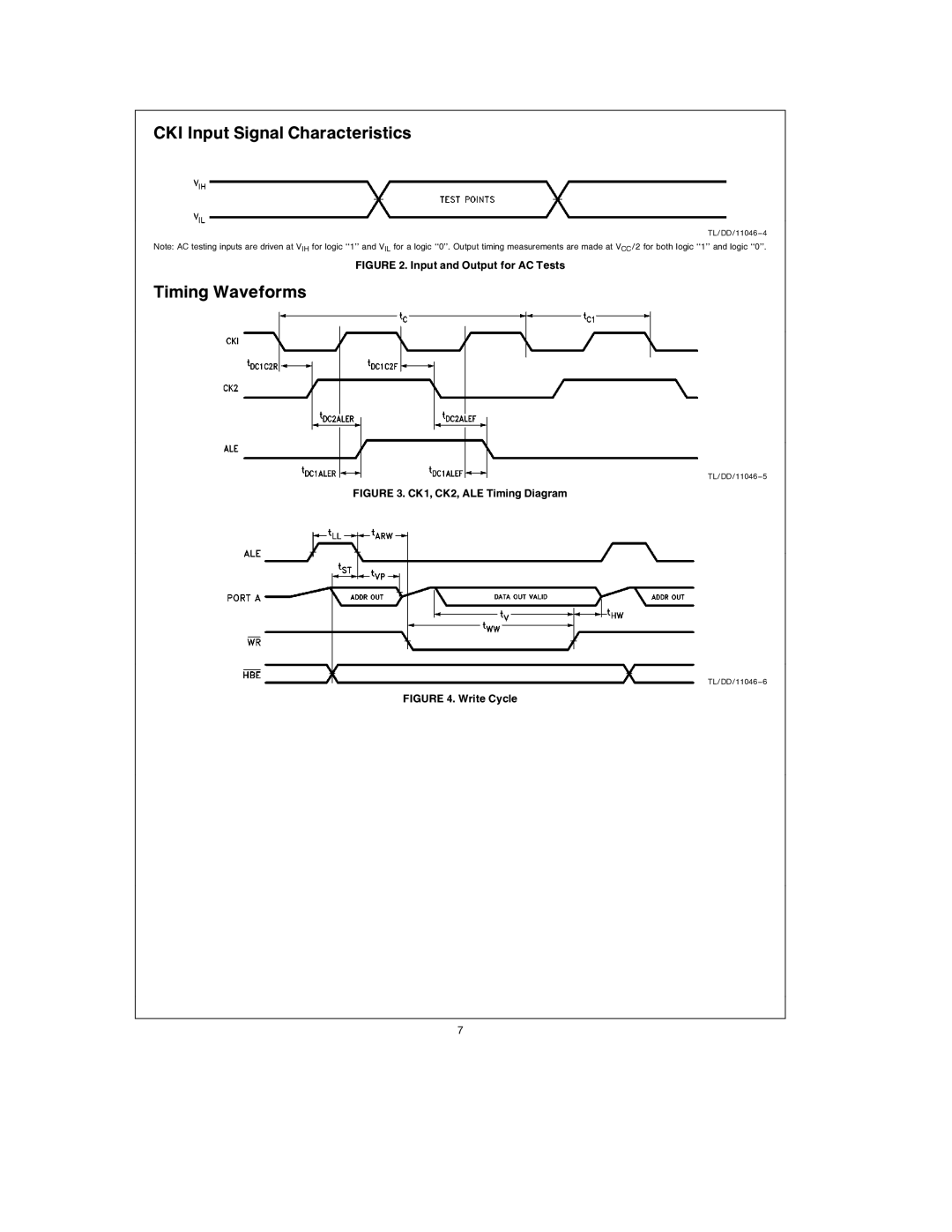
CKI Input Signal Characteristics
TL/DD/11046 – 4
Note: AC testing inputs are driven at VIH for logic ‘‘1’’ and VIL for a logic ‘‘0’’. Output timing measurements are made at VCC/2 for both logic ‘‘1’’ and logic ‘‘0’’.
FIGURE 2. Input and Output for AC Tests
Timing Waveforms
TL/DD/11046 – 5
FIGURE 3. CK1, CK2, ALE Timing Diagram
TL/DD/11046 – 6
FIGURE 4. Write Cycle
7