Director
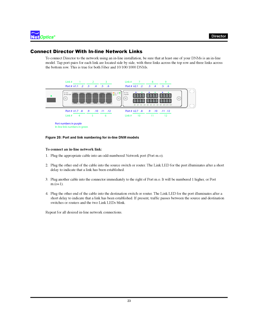
Connect Director With In-line Network Links
To connect Director to the network using an
Link # | 1 |
| 2 | 3 |
Port # n1.1 | .2 | .3 | .4 | .5 . 6 |
|
|
|
| |
10/100/1000 |
|
|
|
|
B |
|
|
|
|
|
| Link # |
| 7 |
|
|
|
| 8 |
|
| 9 |
|
|
|
| Port # n2.1 |
| .2 |
| .3 |
| .4 |
| .5 |
| . 6 |
| |
10 | LINK | A |
| B |
| A |
| B |
| A |
| B |
| |
100 | ACT | GigaBit |
|
|
|
|
|
|
|
|
|
|
|
|
1000 |
|
|
|
|
|
|
|
|
|
|
|
|
| |
|
|
| 1 | 2 | 3 | 4 | 5 | 6 | 7 | 8 | 9 | 10 | 11 | 12 |
Port # | n1.7 | .8 | .9 | .10 .11 .12 | Port # n2.7 .8 | .9 .10 | .11 .12 | |
Link # |
| 4 | 5 | 6 | Link # | 10 | 11 | 12 |
Port numbers in purple
Figure 20: Port and link numbering for in-line DNM models
To connect an in-line network link:
1.Plug the appropriate cable into an
2.Plug the other end of the cable into the source switch or router. The Link LED for the port illuminates after a short delay to indicate that a link has been established.
3.Plug another cable into the connector immediately to the right of Port m.o. It will be numbered 1 higher, or Port m.(o+1).
4.Plug the other end of the cable into the destination switch or router. The Link LED for the port illuminates after a short delay to indicate that a link has been established. If present, traffic passes between the source and destination switches or routers and the two Link LEDs blink.
Repeat for all desired
23