Director
Director Architecture
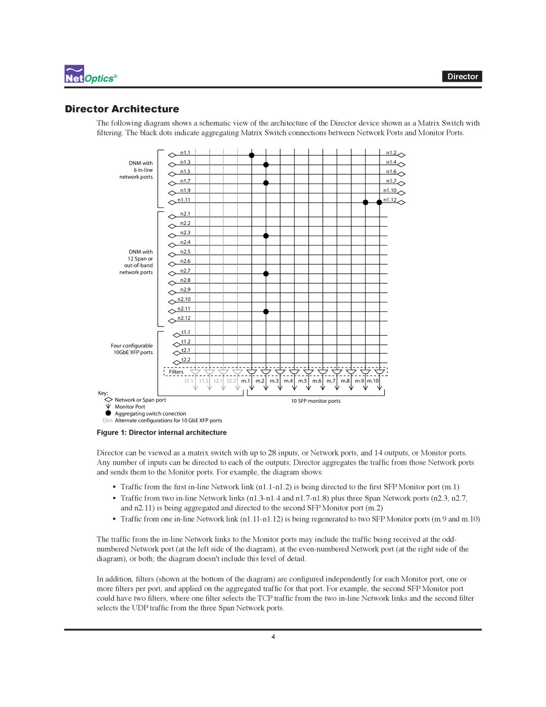
The following diagram shows a schematic view of the architecture of the Director device shown as a Matrix Switch with filtering. The black dots indicate aggregating Matrix Switch connections between Network Ports and Monitor Ports.
DNM with 6
DNM with 12 Span or
Four configurable 10GbE XFP ports
Key:
n1.1 | n1.2 | ||
n1.3 | n1.4 | ||
n1.5 | n1.6 | ||
n1.7 | n1.7 | ||
n1.9 | n1.10 | ||
n1.11 | n1.12 | ||
n2.1 |
|
| |
n2.2 |
|
| |
n2.3 |
|
| |
n2.4 |
|
| |
n2.5 |
|
| |
n2.6 |
|
| |
n2.7 |
|
| |
n2.8 |
|
| |
n2.9 |
|
| |
n2.10 |
|
| |
n2.11 |
|
| |
n2.12 |
|
| |
| t1.1 |
|
|
| t1.2 |
|
|
| t2.1 |
|
|
| t2.2 |
|
|
Filters ![]()
![]()
![]()
![]()
![]()
![]()
![]()
![]()
![]()
![]()
![]()
![]()
![]()
![]() t1.1 t1.2 t2.1 t2.2 m.1 m.2 m.3 m.4 m.5 m.6 m.7 m.8 m.9 m.10
t1.1 t1.2 t2.1 t2.2 m.1 m.2 m.3 m.4 m.5 m.6 m.7 m.8 m.9 m.10
| Network or Span port | 10 SFP monitor ports |
| Monitor Port |
|
|
| |
| Aggregating switch conection |
|
Dim Alternate configurations for 10 GbE XFP ports |
| |
Figure 1: Director internal architecture
Director can be viewed as a matrix switch with up to 28 inputs, or Network ports, and 14 outputs, or Monitor ports. Any number of inputs can be directed to each of the outputs; Director aggregates the traffic from those Network ports and sends them to the Monitor ports. For example, the diagram shows:
•Traffic from the first
•Traffic from two
•Traffic from one
The traffic from the
In addition, filters (shown at the bottom of the diagram) are configured independently for each Monitor port, one or more filters per port, and applied on the aggregated traffic for that port. For example, the second SFP Monitor port could have two filters, where one filter selects the TCP traffic from the two
4