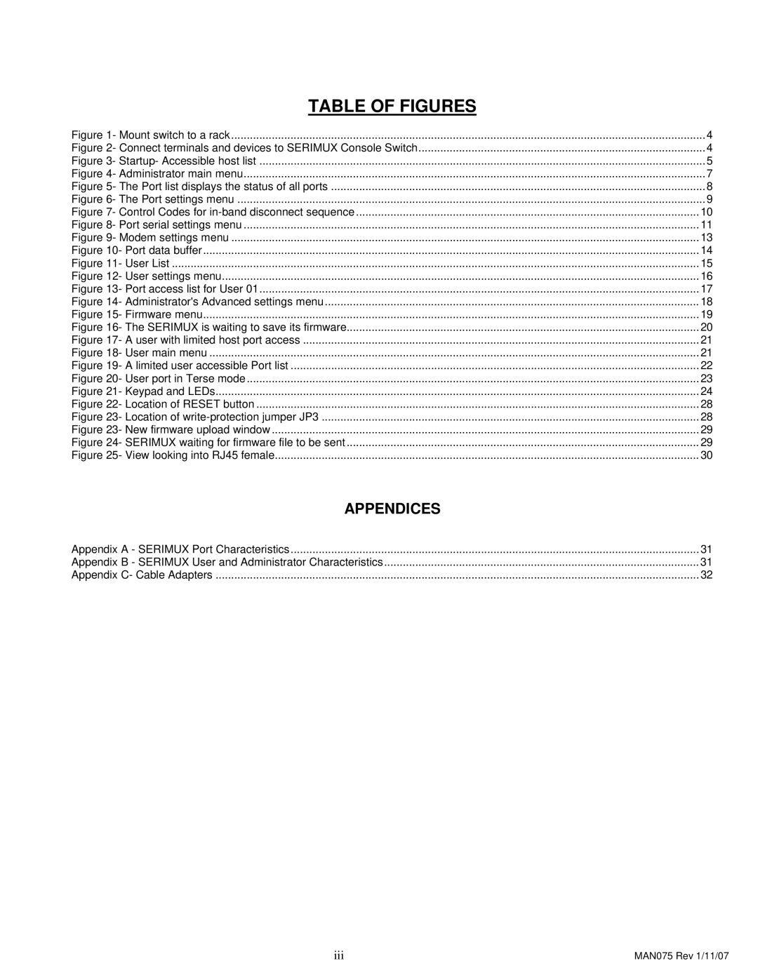
TABLE OF FIGURES |
|
Figure 1- Mount switch to a rack | 4 |
Figure 2- Connect terminals and devices to SERIMUX Console Switch | 4 |
Figure 3- Startup- Accessible host list | 5 |
Figure 4- Administrator main menu | 7 |
Figure 5- The Port list displays the status of all ports | 8 |
Figure 6- The Port settings menu | 9 |
Figure 7- Control Codes for | 10 |
Figure 8- Port serial settings menu | 11 |
Figure 9- Modem settings menu | 13 |
Figure 10- Port data buffer | 14 |
Figure 11- User List | 15 |
Figure 12- User settings menu | 16 |
Figure 13- Port access list for User 01 | 17 |
Figure 14- Administrator's Advanced settings menu | 18 |
Figure 15- Firmware menu | 19 |
Figure 16- The SERIMUX is waiting to save its firmware | 20 |
Figure 17- A user with limited host port access | 21 |
Figure 18- User main menu | 21 |
Figure 19- A limited user accessible Port list | 22 |
Figure 20- User port in Terse mode | 23 |
Figure 21- Keypad and LEDs | 24 |
Figure 22- Location of RESET button | 28 |
Figure 23- Location of | 28 |
Figure 23- New firmware upload window | 29 |
Figure 24- SERIMUX waiting for firmware file to be sent | 29 |
Figure 25- View looking into RJ45 female | 30 |
APPENDICES |
|
Appendix A - SERIMUX Port Characteristics | 31 |
Appendix B - SERIMUX User and Administrator Characteristics | 31 |
Appendix C- Cable Adapters | 32 |
iii | MAN075 Rev 1/11/07 |
