NTI SERIMUX SERIES CONSOLE SWITCH
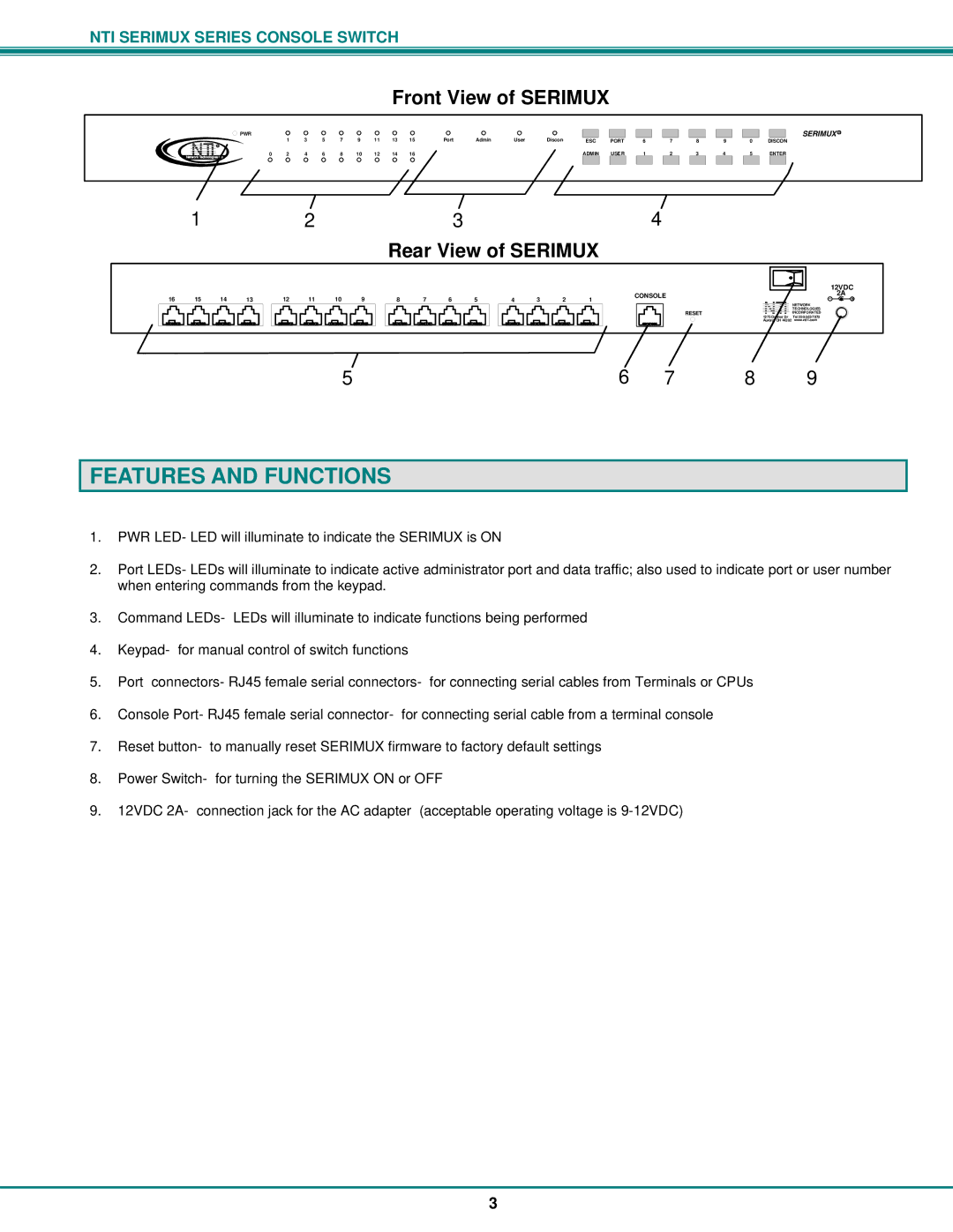
Front View of SERIMUX
| PWR | 1 | 3 | 5 | 7 | 9 | 11 | 13 | 15 | Port | Admin | User | Discon |
|
|
|
|
|
|
| ESC | PORT | 6 | 7 | 8 | ||||||||||||
R |
|
|
|
|
|
|
|
|
|
|
|
|
|
|
|
|
|
|
NetworkNTITechnologies | 0 | 2 | 4 | 6 | 8 | 10 | 12 | 14 | 16 |
|
|
|
| ADMIN | USER | 1 | 2 | 3 |
SERIMUX R
9 | 0 | DISCON | ||
4 | 5 | ENTER | ||
|
|
|
|
|
1 | 2 | 3 |
|
|
| 4 |
|
|
|
|
|
|
| ||||
|
|
|
| Rear View of SERIMUX |
|
|
|
|
|
|
|
|
|
|
| ||
|
|
|
|
|
|
|
|
|
|
|
|
|
|
|
| 12VDC | |
|
|
|
|
|
|
|
|
|
|
|
|
|
|
|
| ||
16 15 14 13 | 12 11 10 9 | 8 7 6 5 | 4 3 2 1 |
| CONSOLE |
|
|
|
| - | 2A + | ||||||
|
|
|
|
|
|
|
|
|
|
|
|
|
|
| NETWORK |
| |
|
|
|
|
|
|
|
|
|
|
| RESET |
|
|
| TECHNOLOGIES |
| |
|
|
|
|
|
|
|
|
|
|
|
|
|
| INCORPORATED |
| ||
|
|
|
|
|
|
|
|
|
|
| 1275 Dr |
| |||||
|
|
|
|
|
|
|
|
|
|
|
|
| |||||
|
|
|
|
|
|
|
|
|
|
|
| Aurora, OH 44202 | www.nti1.com |
| |||
| 5 |
|
|
|
| 6 | 7 | 8 |
|
|
| 9 |
| ||||
FEATURES AND FUNCTIONS
1.PWR LED- LED will illuminate to indicate the SERIMUX is ON
2.Port LEDs- LEDs will illuminate to indicate active administrator port and data traffic; also used to indicate port or user number when entering commands from the keypad.
3.Command LEDs- LEDs will illuminate to indicate functions being performed
4.Keypad- for manual control of switch functions
5.Port connectors- RJ45 female serial connectors- for connecting serial cables from Terminals or CPUs
6.Console Port- RJ45 female serial connector- for connecting serial cable from a terminal console
7.Reset button- to manually reset SERIMUX firmware to factory default settings
8.Power Switch- for turning the SERIMUX ON or OFF
9.12VDC 2A- connection jack for the AC adapter (acceptable operating voltage is
3