NTI RACK MOUNT CONSOLE TERMINAL WITH CONSOLE SWITCH
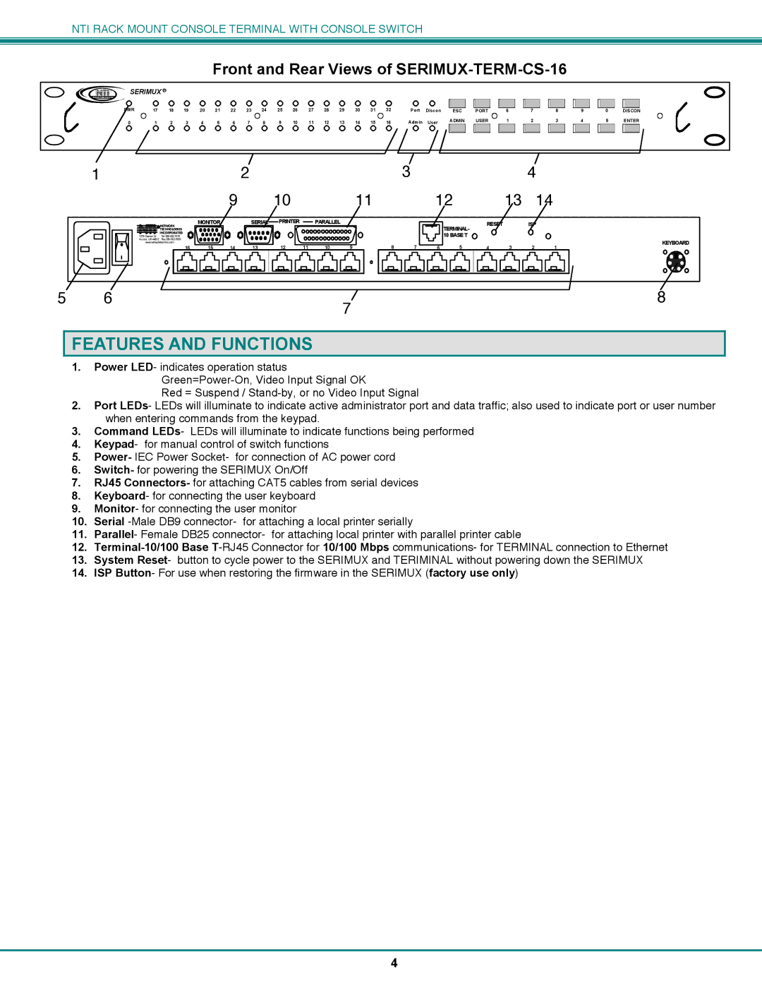
Front and Rear Views of SERIMUX-TERM-CS-16
| NTI |
| SERIMUX R |
|
|
|
|
|
|
|
|
|
|
|
|
|
|
|
|
|
|
|
|
|
|
|
|
|
|
|
|
|
|
|
| |
Network T echnologies | Inc |
|
|
|
|
|
|
|
|
|
|
|
|
|
|
|
|
|
|
|
|
|
|
|
|
|
|
|
|
|
|
|
|
| ||
|
|
| PWR | 17 | 18 | 19 | 20 | 21 | 22 | 23 | 24 | 25 | 26 | 27 | 28 | 29 | 30 | 31 | 32 | Port |
|
|
|
|
|
|
|
|
|
|
|
|
|
|
|
|
|
|
| Discon |
|
| 6 | 7 | 8 |
| 9 |
| 0 |
|
| ||||||||||||||||||||||
|
|
| ESC | PORT |
|
| DISCON | |||||||||||||||||||||||||||||
|
|
| 0 | 1 | 2 | 3 | 4 | 5 | 6 | 7 | 8 | 9 | 10 | 11 | 12 | 13 | 14 | 15 | 16 | Admin | User | ADMIN | USER | 1 | 2 | 3 |
| 4 |
| 5 | ENTER | |||||
|
|
|
|
|
|
|
|
|
|
|
|
|
|
|
|
|
|
|
|
|
|
|
|
|
|
|
|
|
|
|
|
|
|
|
|
|
1 |
|
|
|
|
|
|
| 2 |
|
|
|
|
|
| 3 | |
|
|
|
|
|
|
|
| 9 |
| 10 |
|
|
| 11 |
| |
|
|
|
| R NETWORK | MONITOR |
| SERIAL | PRINTER |
| PARALLEL |
|
|
|
| ||
|
|
|
|
|
|
|
|
|
|
|
|
|
| |||
|
|
|
| NTI1275 Danner Dr | TECHNOLOGIES |
|
|
|
|
|
|
|
|
|
| |
|
|
|
| INCORPORATED |
|
|
|
|
|
|
|
|
|
| ||
|
|
|
|
|
|
|
|
|
|
|
|
|
| |||
|
|
|
| Aurora, OH 44202 |
|
|
|
|
|
|
|
|
|
| ||
|
|
|
| www.networktechinc.com |
|
|
|
|
|
| 9 | 8 | 7 | |||
|
|
|
|
| 16 | 15 | 14 | 13 | 12 | 11 | 10 | |||||
|
|
|
|
|
|
|
|
|
|
|
|
|
|
|
|
|
|
|
|
|
|
|
|
|
|
|
|
|
|
|
|
|
|
|
|
|
|
|
|
|
|
|
|
|
|
|
|
|
|
|
|
|
|
|
|
|
|
|
|
|
|
|
|
|
|
|
|
|
|
|
| 4 |
|
|
|
|
12 |
| 13 | 14 |
|
|
|
| |
| TERMINAL- | RESET |
|
|
|
|
|
|
|
|
|
|
|
|
| ||
|
|
|
|
|
|
|
| |
| 10 BASE T |
|
|
|
|
|
|
|
| 5 | 4 | 3 | 2 | 1 | KEYBOARD | ||
6 |
|
|
| |||||
|
|
|
|
|
|
|
|
|
|
|
|
|
|
|
|
|
|
5 | 6 | 8 |
|
| 7 |
FEATURES AND FUNCTIONS
1.Power LED- indicates operation status
Red = Suspend /
2.Port LEDs- LEDs will illuminate to indicate active administrator port and data traffic; also used to indicate port or user number when entering commands from the keypad.
3.Command LEDs- LEDs will illuminate to indicate functions being performed
4.Keypad- for manual control of switch functions
5.Power- IEC Power Socket- for connection of AC power cord
6.Switch- for powering the SERIMUX On/Off
7.RJ45 Connectors- for attaching CAT5 cables from serial devices
8.Keyboard- for connecting the user keyboard
9.Monitor- for connecting the user monitor
10.Serial
11.Parallel- Female DB25 connector- for attaching local printer with parallel printer cable
12.
13.System Reset- button to cycle power to the SERIMUX and TERIMINAL without powering down the SERIMUX
14.ISP Button- For use when restoring the firmware in the SERIMUX (factory use only)
4
