ENGLISH
SERVICE MANUAL
HYDRAULIC SYSTEM
SUCTION FAN CONTROL VALVE ASSEMBLY REMOVAL/INSTALLATION
CAUTION!
This procedure must be performed with the hopper (3) fully lowered.
CAUTION!
If necessary, remove the bonded sealing washers and replace them.
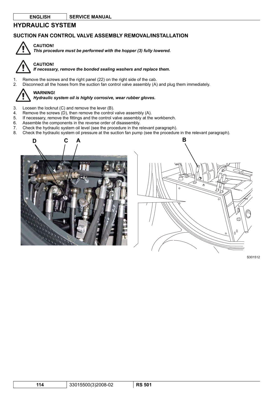
1.Remove the screws and the right panel (22) on the right side of the cab.
2.Disconnect all the hoses from the suction fan control valve assembly (A) and plug them immediately.
WARNING!
Hydraulic system oil is highly corrosive, wear rubber gloves.
3.Loosen the locknut (C) and remove the lever (B).
4.Remove the screws (D), then remove the control valve assembly (A).
5.If necessary, remove the fittings and the control valve assembly at the workbench.
6.Assemble the components in the reverse order of disassembly.
7.Check the hydraulic system oil level (see the procedure in the relevant paragraph).
8.Check the hydraulic system oil pressure at the suction fan pump (see the procedure in the relevant paragraph).
D C AB
S301512
114
RS 501