Front and rear panel
Front panel
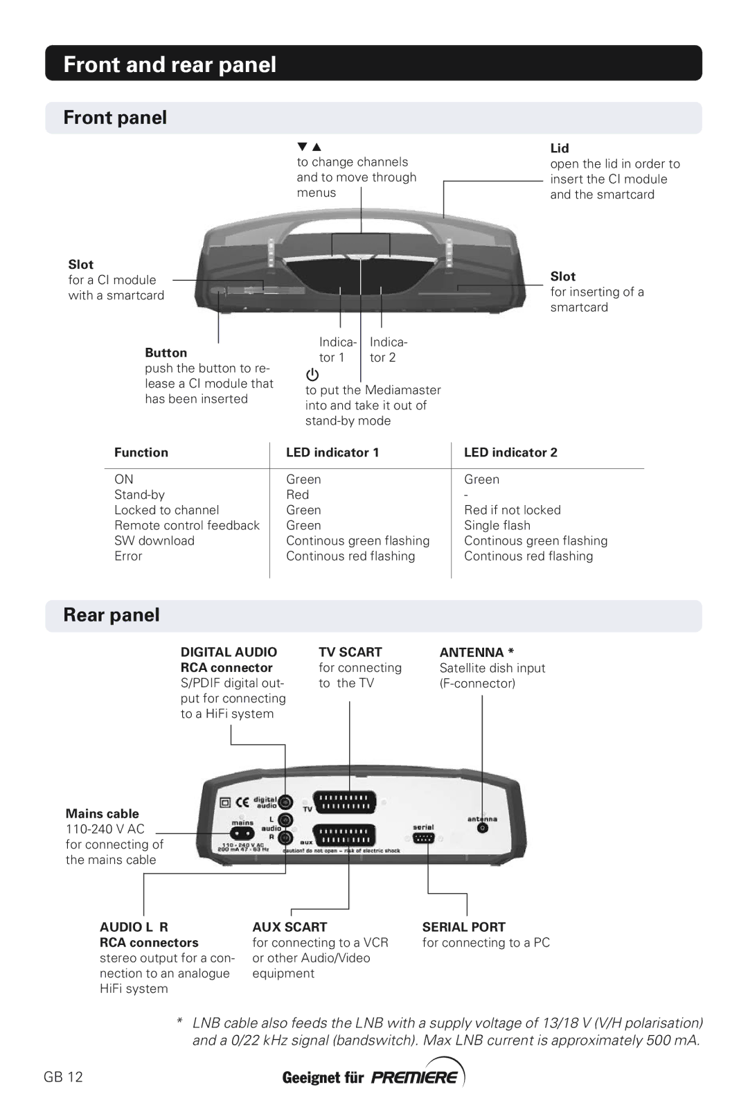
to change channels and to move through menus
Lid
open the lid in order to insert the CI module and the smartcard
Slot
for a CI module with a smartcard
Button
push the button to re- lease a CI module that has been inserted
|
|
|
|
|
|
|
|
Indica- | Indica- | ||
tor 1 | tor 2 | ||
|
|
|
|
to put the Mediamaster into and take it out of
Slot
for inserting of a smartcard
Function | LED indicator 1 | LED indicator 2 |
|
|
|
ON | Green | Green |
Red | - | |
Locked to channel | Green | Red if not locked |
Remote control feedback | Green | Single flash |
SW download | Continous green flashing | Continous green flashing |
Error | Continous red flashing | Continous red flashing |
|
|
|
Rear panel
DIGITAL AUDIO | TV SCART | ANTENNA * | |||
RCA connector | for connecting | Satellite dish input | |||
S/PDIF digital out- | to the TV | ||||
put for connecting |
|
|
| ||
to a HiFi system |
|
|
| ||
|
|
|
|
|
|
|
|
|
|
|
|
|
|
|
|
|
|
Mains cable
AUDIO L R RCA connectors stereo output for a con- nection to an analogue HiFi system
AUX SCART | SERIAL PORT |
for connecting to a VCR | for connecting to a PC |
or other Audio/Video |
|
equipment |
|
*LNB cable also feeds the LNB with a supply voltage of 13/18 V (V/H polarisation) and a 0/22 kHz signal (bandswitch). Max LNB current is approximately 500 mA.
GB 12