Verifying Operation of the Supply Air Limit Switch
To verify operation of the supply air limit switch, make sure that the blower door is in place and that there is power to the furnace. Completely block the return airflow to the fur- nace by installing a
DESCRIPTION OF COMPONENTS
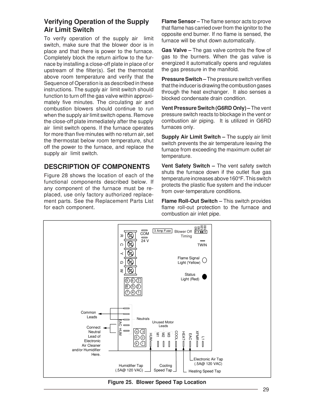
Figure 28 shows the location of each of the functional components described below. If any component of the furnace must be re- placed, use only factory authorized replace- ment parts. See the Replacement Parts List for each component.
Flame Sensor – The flame sensor acts to prove that flame has carried over from the ignitor to the opposite end burner. If no flame is sensed, the furnace will be shut down automatically.
Gas Valve – The gas valve controls the flow of gas to the burners. When the gas valve is energized it automatically opens and regulates the gas pressure in the manifold.
Pressure Switch – The pressure switch verifies that the inducer is drawing the combustion gases through the heat exchanger. It also senses a blocked condensate drain condition.
Vent Pressure Switch (G6RD Only) – The vent pressure switch reacts to blockage in the vent or combustion air piping. It is utilized in G6RD furnaces only.
Supply Air Limit Switch – The supply air limit switch prevents the air temperature leaving the furnace from exceeding the maximum outlet air temperature.
Vent Safety Switch – The vent safety switch shuts the furnace down if the outlet flue gas temperature increases above 160°F. This switch protects the plastic flue system and the inducer from
Flame
| R | |
| C | |
| Y | |
| G | |
| W | |
Common |
| |
Leads | EAC | |
Connect | ||
HUM | ||
Neutral | ||
| ||
Lead of |
| |
Electronic |
| |
Air Cleaner |
| |
and/or Humidifier |
| |
Here. |
|
3 Amp Fuse
COM
24 V
9 | 6 | 3 |
8 | 5 | 2 |
7 | 4 | 1 |
Neutrals
|
|
| Unused Motor | |||
|
|
| Leads | |||
6 | 3 | HUM | M1 | M2 | M3 | |
5 | 2 | |||||
|
|
|
| |||
4 | 1 |
|
|
|
| |
60 90 | 120 | 180 | |
Blower Off |
|
|
|
|
|
|
|
Timing |
|
| |
TWIN
Flame Signal
Light (Yellow)
Status
Light (Red)
COOL | HEAT | EAC | XFMR | L1 |
Humidifier Tap | Cooling |
(.5A@ 120 VAC) | Speed Tap |
Electronic Air Tap (.5A@ 120 VAC)
Heating Speed Tap
Figure 25. Blower Speed Tap Location
29