Upflow Furnaces
Support System on
Vertical Rise Below Joints
Support System with |
|
first support as close | 5' |
to furnace as Possible
Combustion
Air Pipe
Exhaust
Vent
![]()
![]()
![]()
![]()
![]()
![]()
![]()
![]()
![]()
![]()
![]()
![]() Straight Neoprene
Straight Neoprene![]()
![]()
![]()
![]()
![]()
![]()
![]()
![]()
Couplings with
2 Hose Clamps*
(Optional - Not
Shown)
![]() Upward Pitch 1/4" per Foot
Upward Pitch 1/4" per Foot
![]() Cabinet
Cabinet
Furnace Front
Downflow Furnaces
Exhaust
Vent
Support System on
Vertical Rise Below Joints
Support System with |
|
first support as close | 5' |
to furnace as Possible |
|
Combustion |
|
Air Pipe |
|
Straight Neoprene |
|
Rubber Couplings | Upward Pitch |
with 2 Hose Clamps* | 1/4" per Foot |
![]() Cabinet
Cabinet
Furnace Front
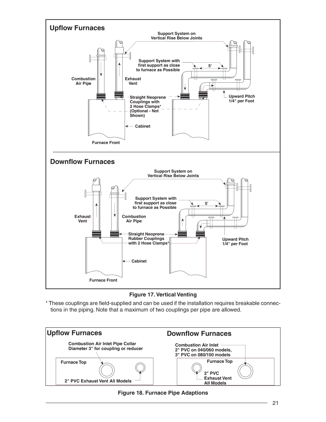
Figure 17. Vertical Venting
*These couplings are
Upflow Furnaces
Combustion Air Inlet Pipe Collar Diameter 3" for coupling or reducer
Furnace Top
2" PVC Exhaust Vent All Models
Downflow Furnaces
Combustion Air Inlet
2" PVC on 040/060 models, 3" PVC on 080/100 models
Furnace Top
2" PVC
Exhaust Vent
All Models
Figure 18. Furnace Pipe Adaptions
21