APPLICATION | SINGLE PIPE LENGTH (ft.) |
| DIRECT VENT, DUAL PIPE LENGTH (ft.) |
| ||||||
| with 1 long radius elbow* |
| with 1 long radius elbow on each pipe* |
| ||||||
PVC,CPVC or ABS | Outlet | Outlet | Inlet/Outlet | Inlet/Outlet | Inlet/Outlet | |||||
SCH. 40 Pipe Size | 2” | 3” | 2” |
| 2” | 3” | 2” | 3” |
| 3” |
Models 040 | 80 | 150 | 40 |
| 40 | 50 | 50 | 90 |
| 90 |
|
|
|
|
|
|
|
|
|
|
|
Models 060 & 080 | 60 | 150 | 30 |
| 30 | 35 | 35 | 90 |
| 90 |
|
|
|
|
|
|
|
|
|
|
|
Models 100 & 120 | 30 | 150 | 15 |
| 15 | 25 | 25 | 90 |
| 90 |
|
|
|
|
|
|
|
|
|
|
|
**NOTES
1.Subtract 2.5 ft. for each additional 2” long radius elbow, 5 ft. for each additional 2” short radius elbow, 3.5’ for each additional 3” long radius elbow, and 7’ for each additional 3” short radius elbow.
2.Two 45 degree elbows are equivalent to one 90 degree elbow.
3.Do not include termination elbows in calculation of vent length
4.This table is applicable for elevations from sea level to 2000 ft. For higher elevations decrease vent pipe lengths by 8% per 1000 ft. of altitude.
5.Only the above pipe materials are approved for use with these condensing furnaces.
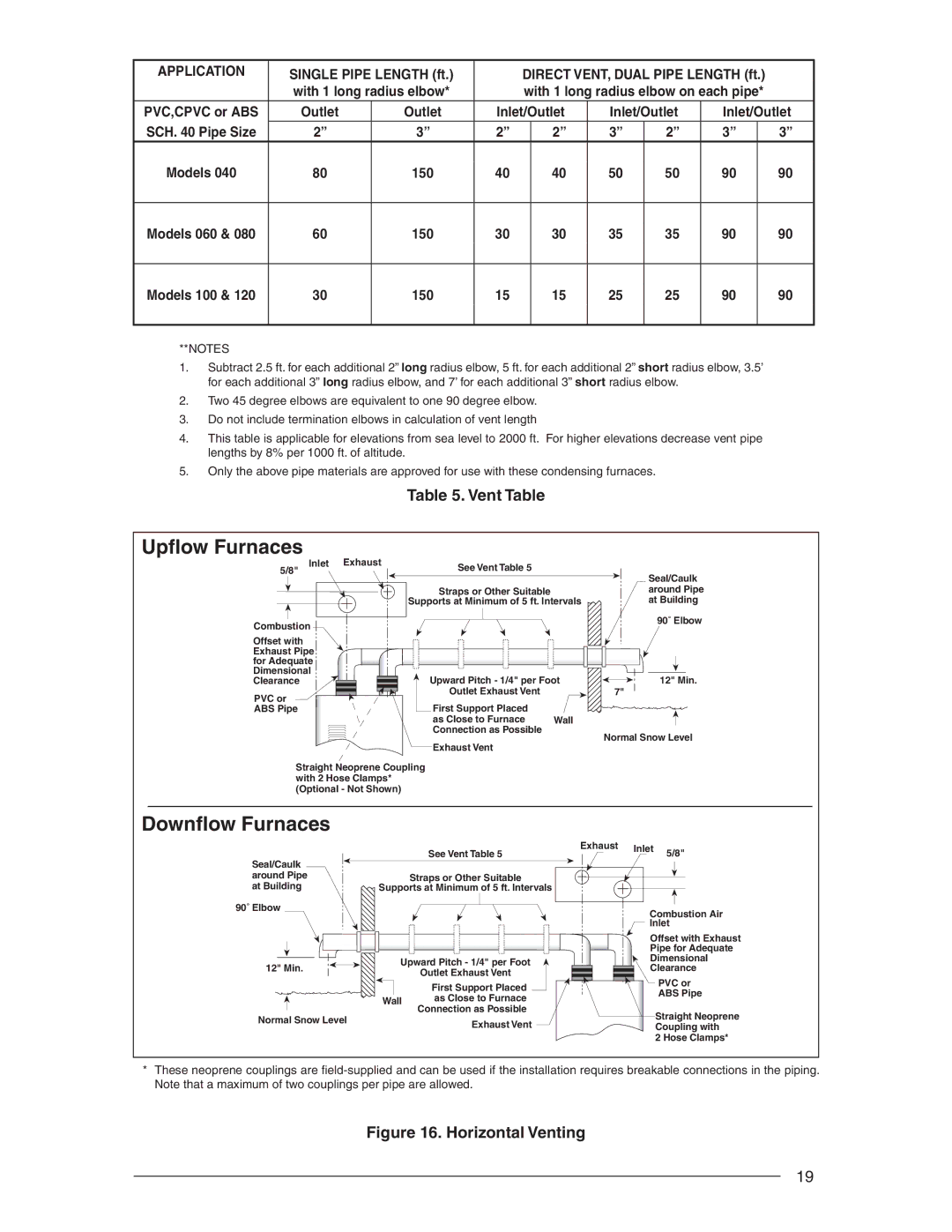
Table 5. Vent Table
Upflow Furnaces
Inlet | Exhaust | See Vent Table 5 |
|
|
5/8" |
|
| Seal/Caulk | |
|
|
| ||
|
|
|
| |
|
| Straps or Other Suitable |
| around Pipe |
|
| Supports at Minimum of 5 ft. Intervals | at Building | |
Combustion |
|
|
| 90˚ Elbow |
|
|
|
| |
Offset with |
|
|
|
|
Exhaust Pipe |
|
|
|
|
for Adequate |
|
|
|
|
Dimensional |
| Upward Pitch - 1/4" per Foot | 12" Min. | |
Clearance |
| |||
PVC or |
| Outlet Exhaust Vent |
| 7" |
| First Support Placed |
|
| |
ABS Pipe |
|
|
| |
|
| as Close to Furnace | Wall |
|
|
| Connection as Possible |
| Normal Snow Level |
|
| Exhaust Vent |
| |
|
|
|
| |
Straight Neoprene Coupling |
|
| ||
with 2 Hose Clamps* |
|
|
| |
(Optional - Not Shown) |
|
|
| |
Downflow Furnaces
Seal/Caulk around Pipe at Building
90˚ Elbow
12" Min.
See Vent Table 5
Straps or Other Suitable
Supports at Minimum of 5 ft. Intervals
Upward Pitch - 1/4" per Foot
Outlet Exhaust Vent
Exhaust Inlet 5/8"
Combustion Air
Inlet
Offset with Exhaust
Pipe for Adequate
Dimensional
Clearance
|
| First Support Placed |
| Wall | as Close to Furnace |
| Connection as Possible | |
Normal Snow Level |
| |
| Exhaust Vent | |
|
|
PVC or
ABS Pipe
Straight Neoprene Coupling with
2 Hose Clamps*
*These neoprene couplings are
Figure 16. Horizontal Venting
19