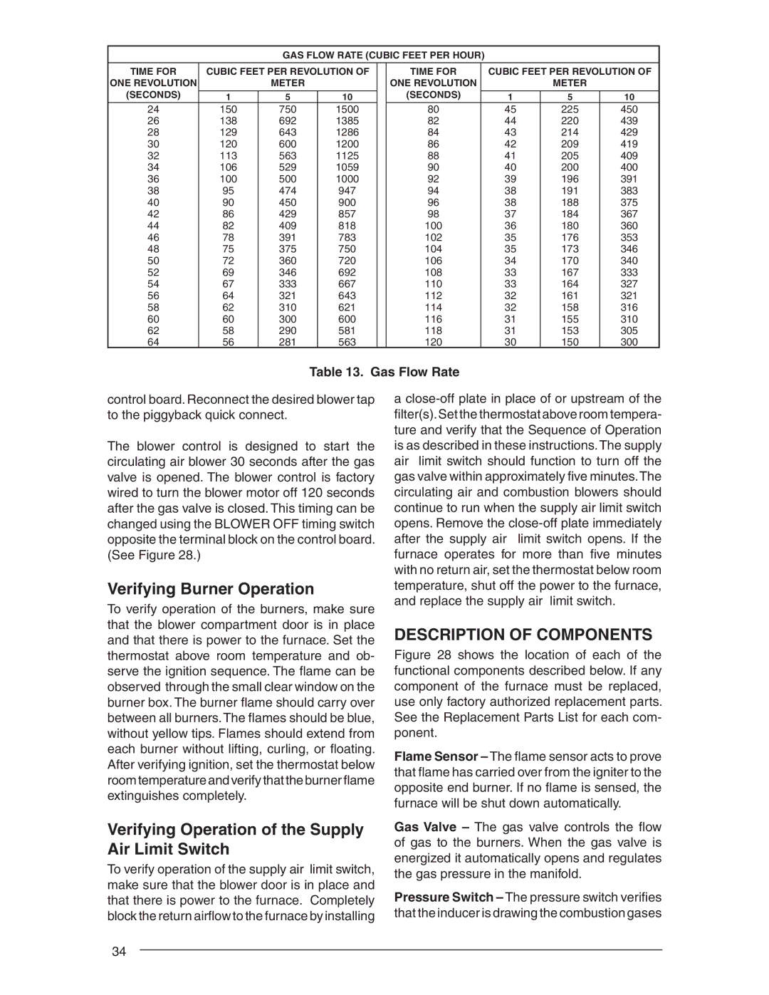
GAS FLOW RATE (CUBIC FEET PER HOUR)
TIME FOR | CUBIC FEET PER REVOLUTION OF |
| TIME FOR | CUBIC FEET PER REVOLUTION OF | ||||
ONE REVOLUTION |
| METER |
|
| ONE REVOLUTION |
| METER |
|
(SECONDS) |
|
|
|
| (SECONDS) |
|
|
|
1 | 5 | 10 |
| 1 | 5 | 10 | ||
24 | 150 | 750 | 1500 |
| 80 | 45 | 225 | 450 |
26 | 138 | 692 | 1385 |
| 82 | 44 | 220 | 439 |
28 | 129 | 643 | 1286 |
| 84 | 43 | 214 | 429 |
30 | 120 | 600 | 1200 |
| 86 | 42 | 209 | 419 |
32 | 113 | 563 | 1125 |
| 88 | 41 | 205 | 409 |
34 | 106 | 529 | 1059 |
| 90 | 40 | 200 | 400 |
36 | 100 | 500 | 1000 |
| 92 | 39 | 196 | 391 |
38 | 95 | 474 | 947 |
| 94 | 38 | 191 | 383 |
40 | 90 | 450 | 900 |
| 96 | 38 | 188 | 375 |
42 | 86 | 429 | 857 |
| 98 | 37 | 184 | 367 |
44 | 82 | 409 | 818 |
| 100 | 36 | 180 | 360 |
46 | 78 | 391 | 783 |
| 102 | 35 | 176 | 353 |
48 | 75 | 375 | 750 |
| 104 | 35 | 173 | 346 |
50 | 72 | 360 | 720 |
| 106 | 34 | 170 | 340 |
52 | 69 | 346 | 692 |
| 108 | 33 | 167 | 333 |
54 | 67 | 333 | 667 |
| 110 | 33 | 164 | 327 |
56 | 64 | 321 | 643 |
| 112 | 32 | 161 | 321 |
58 | 62 | 310 | 621 |
| 114 | 32 | 158 | 316 |
60 | 60 | 300 | 600 |
| 116 | 31 | 155 | 310 |
62 | 58 | 290 | 581 |
| 118 | 31 | 153 | 305 |
64 | 56 | 281 | 563 |
| 120 | 30 | 150 | 300 |
Table 13. Gas Flow Rate
control board. Reconnect the desired blower tap to the piggyback quick connect.
The blower control is designed to start the circulating air blower 30 seconds after the gas valve is opened. The blower control is factory wired to turn the blower motor off 120 seconds after the gas valve is closed. This timing can be changed using the BLOWER OFF timing switch opposite the terminal block on the control board. (See Figure 28.)
Verifying Burner Operation
To verify operation of the burners, make sure that the blower compartment door is in place and that there is power to the furnace. Set the thermostat above room temperature and ob- serve the ignition sequence. The flame can be observed through the small clear window on the burner box. The burner flame should carry over between all burners. The flames should be blue, without yellow tips. Flames should extend from each burner without lifting, curling, or floating. After verifying ignition, set the thermostat below room temperature and verify that the burner flame extinguishes completely.
Verifying Operation of the Supply Air Limit Switch
To verify operation of the supply air limit switch, make sure that the blower door is in place and that there is power to the furnace. Completely block the return airflow to the furnace by installing
a
DESCRIPTION OF COMPONENTS
Figure 28 shows the location of each of the functional components described below. If any component of the furnace must be replaced, use only factory authorized replacement parts. See the Replacement Parts List for each com- ponent.
Flame Sensor – The flame sensor acts to prove that flame has carried over from the igniter to the opposite end burner. If no flame is sensed, the furnace will be shut down automatically.
Gas Valve – The gas valve controls the flow of gas to the burners. When the gas valve is energized it automatically opens and regulates the gas pressure in the manifold.
Pressure Switch – The pressure switch verifies that the inducer is drawing the combustion gases
34
