Model | Furnace |
| Dimensions (inches) |
| Shipping | ||
|
| Weight | |||||
Number | Btuh |
|
|
|
| ||
A | B | C | D | (lbs) | |||
|
| ||||||
|
|
|
|
|
|
| |
*RC040 | 40,000 | 14 1/4 | 12 3/4 | 5 1/8 | 11 3/4 | 133 | |
*RC060 | 60,000 | 14 1/4 | 12 3/4 | 5 1/8 | 11 3/4 | 140 | |
*RC080 | 80,000 | 19 3/4 | 18 1/4 | 7 7/8 | 17 1/4 | 172 | |
*RC100 | 100,000 | 19 3/4 | 18 1/4 | 7 7/8 | 17 1/4 | 180 | |
*RC120 | 120,000 | 22 1/2 | 21 | 9 1/4 | 20 | 204 | |
*RL040 | 40,000 | 14 1/4 | 12 3/4 | 4 5/8 | 12 3/4 | 135 | |
*RL060 | 60,000 | 14 1/4 | 12 3/4 | 4 5/8 | 12 3/4 | 135 | |
*RL080 | 80,000 | 19 3/4 | 18 1/4 | 10 | 18 1/4 | 174 | |
*RL100 | 100,000 | 19 3/4 | 18 1/4 | 10 | 18 1/4 | 185 | |
*RL120 | 120,000 | 22 1/2 | 21 | 12 1/2 | 21 1/8 | 209 | |
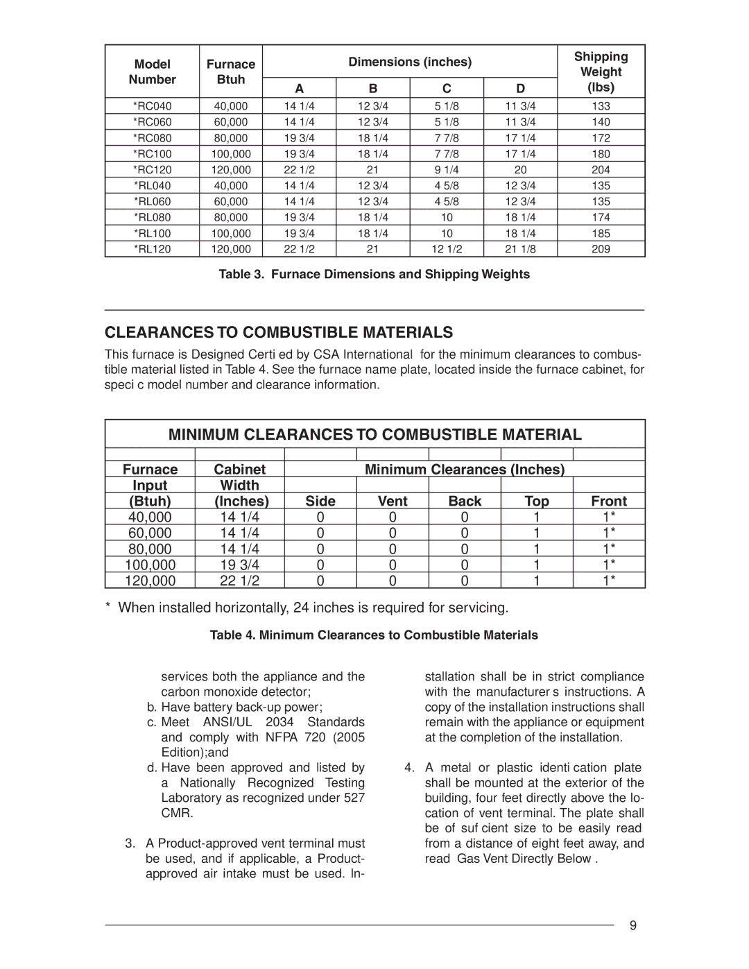
Table 3. Furnace Dimensions and Shipping Weights
CLEARANCES TO COMBUSTIBLE MATERIALS
This furnace is Designed Certified by CSA International for the minimum clearances to combus- tible material listed in Table 4. See the furnace name plate, located inside the furnace cabinet, for specific model number and clearance information.
MINIMUM CLEARANCES TO COMBUSTIBLE MATERIAL
|
|
|
|
|
|
|
Furnace | Cabinet |
| Minimum Clearances (Inches) |
| ||
Input | Width |
|
|
|
|
|
(Btuh) | (Inches) | Side | Vent | Back | Top | Front |
40,000 | 14 1/4 | 0 | 0 | 0 | 1 | 1* |
60,000 | 14 1/4 | 0 | 0 | 0 | 1 | 1* |
80,000 | 14 1/4 | 0 | 0 | 0 | 1 | 1* |
100,000 | 19 3/4 | 0 | 0 | 0 | 1 | 1* |
120,000 | 22 1/2 | 0 | 0 | 0 | 1 | 1* |
* When installed horizontally, 24 inches is required for servicing.
Table 4. Minimum Clearances to Combustible Materials
services both the appliance and the carbon monoxide detector;
b. Have battery
c. Meet ANSI/UL 2034 Standards and comply with NFPA 720 (2005 Edition);and
d. Have been approved and listed by a Nationally Recognized Testing Laboratory as recognized under 527 CMR.
3.A
stallation shall be in strict compliance with the manufacturer’s instructions. A copy of the installation instructions shall remain with the appliance or equipment at the completion of the installation.
4.A metal or plastic identification plate shall be mounted at the exterior of the building, four feet directly above the lo- cation of vent terminal. The plate shall be of sufficient size to be easily read from a distance of eight feet away, and read “Gas Vent Directly Below”.
9
