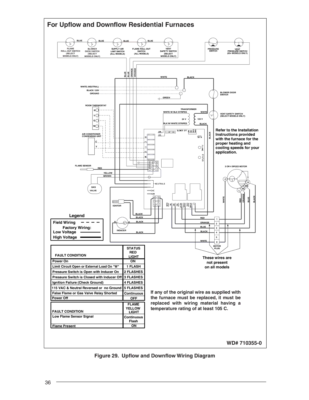
For Upflow and Downflow Residential Furnaces
BLUE | BLUE | BLUE | BLUE |
FLAME | BLOWER | SUPPLY AIR |
| FLAME | |
DECK SWITCH | LIMIT SWITCH |
|
| SWITCH | |
(SELECT | (SELECT | (ALL MODELS) |
|
| (ALL MODELS) |
MODELS ONLY) | MODELS ONLY) |
|
|
|
|
|
| BLUE | BLUE | ORANGE | ORANGE |
| WHITE (NEUTRAL) |
|
|
|
|
| BLACK 120V |
|
|
|
|
| GROUND |
|
|
|
|
| ROOM THERMOSTAT |
|
|
|
|
VENT
SAFETY SWITCH
(SELECT
MODELS ONLY)
WHITE
GREEN
PRESSURE | VENT |
SWITCH | PRESSURE SWITCH |
| (93+ MODELS ONLY) |
BLACK
BLOWER DOOR
SWITCH
|
|
|
|
| R |
|
|
|
|
|
|
|
|
|
|
|
|
|
|
|
| ||
|
|
|
|
| Y |
|
|
|
|
|
|
|
|
|
|
|
|
|
|
|
| ||
|
|
|
|
| G |
|
|
|
|
|
|
|
|
|
|
|
|
|
|
|
| ||
|
|
|
|
| W |
|
|
|
|
|
|
|
|
|
|
|
|
|
|
|
| ||
|
|
|
|
|
|
|
|
|
|
|
|
|
|
|
|
|
|
|
|
|
|
| |
|
|
| AIR CONDITIONER |
|
|
|
|
|
|
|
|
|
|
|
|
| |||||||
|
|
| CONDENSING UNIT |
|
|
|
|
|
|
|
|
|
|
|
|
| |||||||
|
|
|
|
|
| C |
|
|
|
|
|
|
|
|
|
|
|
|
| ||||
|
|
|
|
|
| Y |
|
|
|
|
|
|
|
|
|
|
|
|
| ||||
|
|
|
|
|
|
|
|
|
|
|
|
|
|
|
|
|
|
|
|
| |||
| FLAME SENSOR |
|
|
|
|
|
|
|
|
|
|
|
|
| |||||||||
|
|
|
|
|
|
| RED |
|
|
|
|
|
|
|
|
|
|
|
|
| |||
|
|
|
|
|
|
|
|
|
|
| YELLOW |
|
|
|
|
|
| ||||||
|
|
|
|
|
|
|
|
|
|
| BROWN |
|
|
|
|
|
| ||||||
|
|
|
|
|
|
|
|
|
|
|
|
|
|
|
|
|
|
|
|
|
|
|
|
|
|
|
|
|
|
|
|
|
|
|
|
|
|
|
|
|
|
|
|
|
|
|
|
|
|
|
| GAS |
|
|
|
|
|
|
|
|
|
|
|
|
| ||||||
|
|
|
| VALVE |
|
|
|
|
|
|
|
|
|
|
|
|
| ||||||
|
|
|
|
|
|
|
|
|
|
|
|
|
|
|
|
|
|
|
|
|
|
|
|
|
|
|
|
|
|
|
|
|
|
|
|
|
|
|
|
|
|
|
|
|
|
|
|
|
|
|
|
|
|
|
|
|
|
|
|
| IGNITOR |
|
|
|
|
|
| ||||
| Legend |
|
|
|
|
|
|
|
|
| BLACK |
| |||||||||||
|
|
|
|
|
|
|
|
|
| BLACK |
| ||||||||||||
| Field Wiring |
|
| R | C BLACK |
| |||||||||||||||||
|
|
|
|
|
|
|
|
|
|
|
|
|
| ||||||||||
| Factory Wiring: |
|
|
|
| INDUCER |
| ||||||||||||||||
| Low Voltage |
|
|
|
|
|
|
|
|
|
|
|
|
|
| ||||||||
|
|
|
|
|
|
|
|
|
|
|
| BLACK |
| ||||||||||
|
|
|
|
|
|
|
|
|
|
| |||||||||||||
| High Voltage |
|
|
|
|
|
|
|
|
|
| STATUS |
| ||||||||||
|
|
|
|
|
|
|
|
|
| ||||||||||||||
|
|
|
|
|
|
|
|
|
|
|
|
|
|
|
|
|
|
| |||||
|
|
|
|
|
|
|
|
|
|
|
|
|
|
|
|
|
|
| |||||
|
|
|
|
|
|
|
|
|
|
|
|
|
|
|
|
|
|
| |||||
|
|
|
|
|
|
|
|
|
|
|
|
|
|
|
|
|
|
| |||||
| FAULT CONDITION |
|
|
|
|
|
|
| RED |
| |||||||||||||
|
|
|
|
|
|
|
| LIGHT |
| ||||||||||||||
|
|
|
|
|
|
|
|
|
|
|
|
|
|
|
|
|
|
| |||||
| Power On |
|
|
|
|
|
|
|
| ON |
|
| |||||||||||
| Limit Circuit Open or External Load On "W" |
| 1 FLASH |
|
| ||||||||||||||||||
| Pressure Switch is Open with Inducer On |
| 2 FLASHES |
|
| ||||||||||||||||||
| Pressure Switch is Closed with Inducer Off |
| 3 FLASHES |
|
| ||||||||||||||||||
| Ignition Failure (Check Ground) |
|
|
|
|
|
|
| 4 FLASHES |
|
| ||||||||||||
| 115 VAC & Neutral Reversed or no Ground |
| 5 FLASHES |
| |||||||||||||||||||
|
|
|
|
|
|
| |||||||||||||||||
| False Flame or Gas Valve Relay Shorted |
| Continuous |
|
| ||||||||||||||||||
| Power Off |
|
|
|
|
|
|
|
| OFF |
| ||||||||||||
|
|
|
|
|
|
|
|
|
|
|
|
|
|
|
|
|
|
|
|
|
| ||
|
|
|
|
|
|
|
|
|
|
|
|
|
|
|
|
|
| FLAME |
|
| |||
| FAULT CONDITION |
|
|
|
|
|
|
| YELLOW |
|
| ||||||||||||
|
|
|
|
|
|
|
| LIGHT |
|
| |||||||||||||
| Low Flame Sensor Signal |
|
|
|
|
|
|
| Continuous |
|
| ||||||||||||
|
|
|
|
|
|
|
|
|
|
|
|
|
|
|
|
|
| Flash |
|
| |||
|
|
|
|
|
|
|
|
|
|
|
|
| |||||||||||
| Flame Present |
|
|
|
|
|
|
|
| ON |
|
| |||||||||||
TRANSFORMER |
|
|
WHITE W/ BLK STRIPES | WHITE | VENT SAFETY SWITCH |
|
| |
|
| (SELECT MODELS ONLY) |
24 V | 120 V |
|
BLK W/ WHITE STRIPES | BLACK |
|
180 120 90 60 | BLACK | Refer to the Installation |
Instructions provided | ||
|
| with the furnace for the |
|
| proper heating and |
|
| cooling speeds for your |
|
| application. |
|
| 3 OR 4 SPEED MOTOR |
| ||
|
| C |
|
|
|
|
|
|
| H |
|
|
|
|
| MH |
|
|
| L | ML |
|
|
|
|
|
|
| |
| WHITE | RED | ORANGE | BLUE | BLACK |
RED | 1 |
|
|
|
|
|
|
|
|
| |
ORANGE | 2 |
|
|
|
|
|
|
|
|
| |
BLUE | 3 |
|
|
|
|
|
|
|
|
| |
BLACK | 4 |
|
|
|
|
|
|
|
|
| |
| 5 |
|
|
|
|
WHITE | 6 |
|
|
|
|
|
|
|
|
| |
| MOTOR |
|
|
|
|
| PLUG |
|
|
|
|
These wires are
not present
on all models
If any of the original wire as supplied with the furnace must be replaced, it must be replaced with wiring material having a temperature rating of at least 105 C.
WD# 710355-0
Figure 29. Upflow and Downflow Wiring Diagram
36