PART 3

OPERATION: Configuration Mode

3.1 Introduction

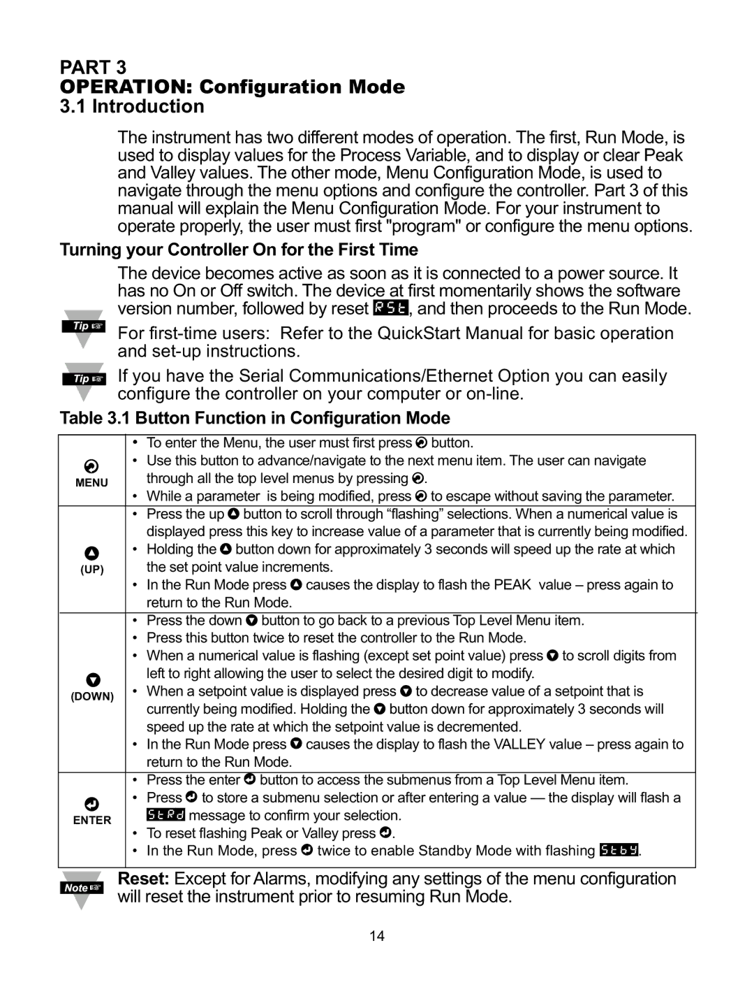
The instrument has two different modes of operation. The first, Run Mode, is used to display values for the Process Variable, and to display or clear Peak and Valley values. The other mode, Menu Configuration Mode, is used to navigate through the menu options and configure the controller. Part 3 of this manual will explain the Menu Configuration Mode. For your instrument to operate properly, the user must first "program" or configure the menu options.

Turning your Controller On for the First Time

The device becomes active as soon as it is connected to a power source. It has no On or Off switch. The device at first momentarily shows the software version number, followed by reset RST, and then proceeds to the Run Mode.

For first-time users: Refer to the QuickStart Manual for basic operation and set-up instructions.

If you have the Serial Communications/Ethernet Option you can easily configure the controller on your computer or on-line.

Table 3.1 Button Function in Configuration Mode

To enter the Menu, the user must first press a button.

a• Use this button to advance/navigate to the next menu item. The user can navigate

MENU

through all the top level menus by pressing a.

While a parameter is being modified, press a to escape without saving the parameter.

Press the up b button to scroll through “flashing” selections. When a numerical value is displayed press this key to increase value of a parameter that is currently being modified.

b• Holding the b button down for approximately 3 seconds will speed up the rate at which

(UP)

the set point value increments.

In the Run Mode press b causes the display to flash the PEAK value – press again to return to the Run Mode.

Press the down c button to go back to a previous Top Level Menu item.

Press this button twice to reset the controller to the Run Mode.

When a numerical value is flashing (except set point value) press c to scroll digits from

cleft to right allowing the user to select the desired digit to modify.

(DOWN)

• When a setpoint value is displayed press c to decrease value of a setpoint that is

currently being modified. Holding the c button down for approximately 3 seconds will


speed up the rate at which the setpoint value is decremented.


• In the Run Mode press c causes the display to flash the VALLEY value – press again to


return to the Run Mode.


• Press the enter d button to access the submenus from a Top Level Menu item.

d• Press d to store a submenu selection or after entering a value — the display will flash a

ENTER

STRD message to confirm your selection.


To reset flashing Peak or Valley press d.

In the Run Mode, press d twice to enable Standby Mode with flashing STBY.

Reset: Except for Alarms, modifying any settings of the menu configuration will reset the instrument prior to resuming Run Mode.

14

Page 18
Image 18
Omega CNI8DH, CNI8DV, CNI16D Part, Operation Configuration Mode Introduction, Turning your Controller On for the First Time

CNI16, CNI32, CNI8DH, CNI8C, CNI16D specifications

The Omega CNI series, including models CNI8DV, CNI8, CNI8DH, CNI32, and CNI16, represents a cutting-edge line of sensors designed for various industrial applications. Known for their reliability and versatile functionality, these sensors play a crucial role in monitoring and controlling multiple parameters in different environments.

The CNI8DV model is equipped with dual voltage outputs, enabling flexibility in integration with various systems. This feature allows users to choose between standard and high voltage operating conditions, making it suitable for a wide range of applications. Its high precision and quick response times deliver accurate measurements, essential for critical processes where timing and accuracy are paramount.

The CNI8 model offers robust performance with an extensive measurement range. This model is particularly noteworthy for its advanced signal processing technology, which improves measurement stability and accuracy. It utilizes digital filtering and calibration techniques to enhance performance and ensure consistent output, minimizing the effects of environmental fluctuations.

In the CNI8DH variant, enhanced durability is a key characteristic. This model features a more robust housing that protects it from harsh environmental conditions. It is designed to withstand high humidity, dust, and varying temperatures, making it suitable for outdoor applications or environments where exposure to elements is a concern. It also includes real-time diagnostics to monitor its operational health, allowing for proactive maintenance.

The CNI32 model stands out with its higher measurement capacity and greater flexibility in configurations. This sensor can handle multiple input types, including temperature, pressure, and flow rates. Its modular design allows users to customize it for specific applications, making it ideal for industries ranging from manufacturing to energy production.

The CNI16 model is designed for standard applications requiring precision and reliability. Its compact size allows for easy installation in tight spaces, while still delivering high performance. Enhanced connectivity options support integration with various data acquisition systems and industrial networks, enabling seamless data collection and monitoring.

In summary, the Omega CNI series exemplifies state-of-the-art sensor technology, offering a range of features that cater to diverse industrial needs. From versatile voltage outputs in the CNI8DV to the rugged design of the CNI8DH, each model is engineered to provide accurate, reliable readings with the ability to withstand challenging conditions. Whether for monitoring environmental conditions or precise measurements in manufacturing processes, the CNI series continues to be a top choice for professionals seeking high-quality sensors.