7.3.3TRIGGER CONTROL/STATUS REGISTER BADR1 + 4
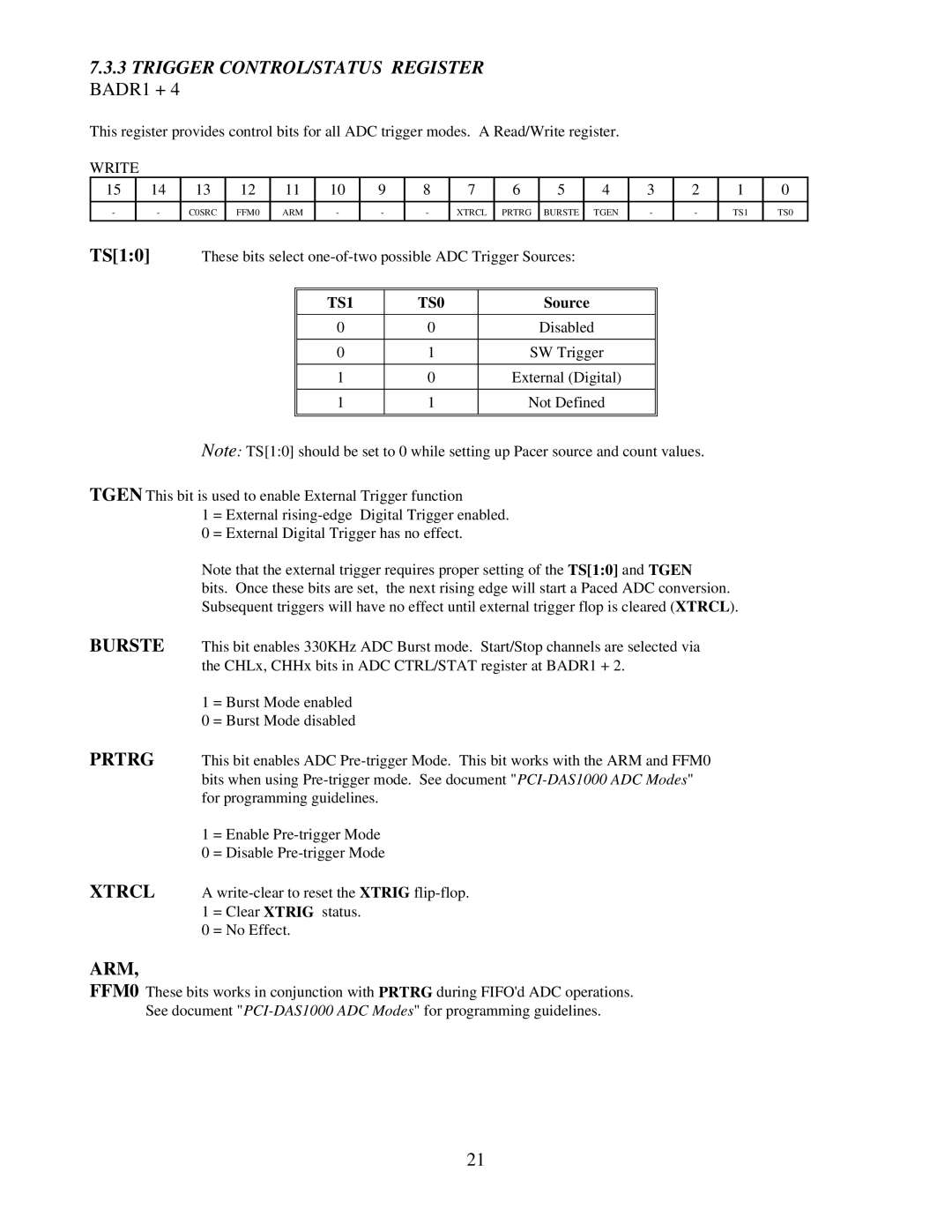
This register provides control bits for all ADC trigger modes. A Read/Write register.
WRITE
15 |
| 14 | 13 | 12 | 11 | 10 | 9 | 8 | 7 |
| 6 | 5 |
| 4 | 3 |
| 2 | 1 | 0 | ||
|
|
|
|
|
|
|
|
|
|
|
|
|
|
|
|
|
|
|
|
|
|
- |
| - | C0SRC | FFM0 | ARM | - | - |
| - | XTRCL | PRTRG | BURSTE |
| TGEN | - |
| - | TS1 | TS0 | ||
|
|
|
|
|
|
|
|
|
|
|
|
|
|
|
|
|
|
|
|
|
|
TS[1:0] |
| These bits select |
|
|
|
|
|
| |||||||||||||
|
|
|
|
|
|
|
|
|
|
|
|
|
|
|
|
|
|
|
|
| |
|
|
|
|
|
|
| TS1 |
|
| TS0 |
|
|
| Source |
|
|
|
|
|
| |
|
|
|
|
|
|
|
|
|
|
|
|
|
|
|
|
|
|
|
| ||
|
|
|
|
|
|
| 0 |
|
| 0 |
|
|
| Disabled |
|
|
|
|
| ||
|
|
|
|
|
|
|
|
|
|
|
|
|
|
|
|
|
|
| |||
|
|
|
|
|
|
| 0 |
|
| 1 |
|
| SW Trigger |
|
|
|
|
| |||
|
|
|
|
|
|
|
|
|
|
|
|
|
|
|
|
|
|
| |||
|
|
|
|
|
|
| 1 |
|
| 0 |
|
| External (Digital) |
|
|
|
|
| |||
|
|
|
|
|
|
|
|
|
|
|
|
|
|
|
|
|
|
| |||
|
|
|
|
|
|
| 1 |
|
| 1 |
|
| Not Defined |
|
|
|
|
| |||
|
|
|
|
|
|
|
|
|
|
|
|
|
|
|
|
|
|
|
|
|
|
|
|
|
|
|
|
|
|
|
|
|
|
|
|
|
|
|
|
|
|
|
|
Note: TS[1:0] should be set to 0 while setting up Pacer source and count values.
TGEN This bit is used to enable External Trigger function
1 = External
0 = External Digital Trigger has no effect.
Note that the external trigger requires proper setting of the TS[1:0] and TGEN
bits. Once these bits are set, the next rising edge will start a Paced ADC conversion. Subsequent triggers will have no effect until external trigger flop is cleared (XTRCL).
BURSTE This bit enables 330KHz ADC Burst mode. Start/Stop channels are selected via the CHLx, CHHx bits in ADC CTRL/STAT register at BADR1 + 2.
1 = Burst Mode enabled
0 = Burst Mode disabled
PRTRG This bit enables ADC
1= Enable
0= Disable
XTRCL A
1 = Clear XTRIG status.
0 = No Effect.
ARM,
FFM0 These bits works in conjunction with PRTRG during FIFO'd ADC operations. See document
21