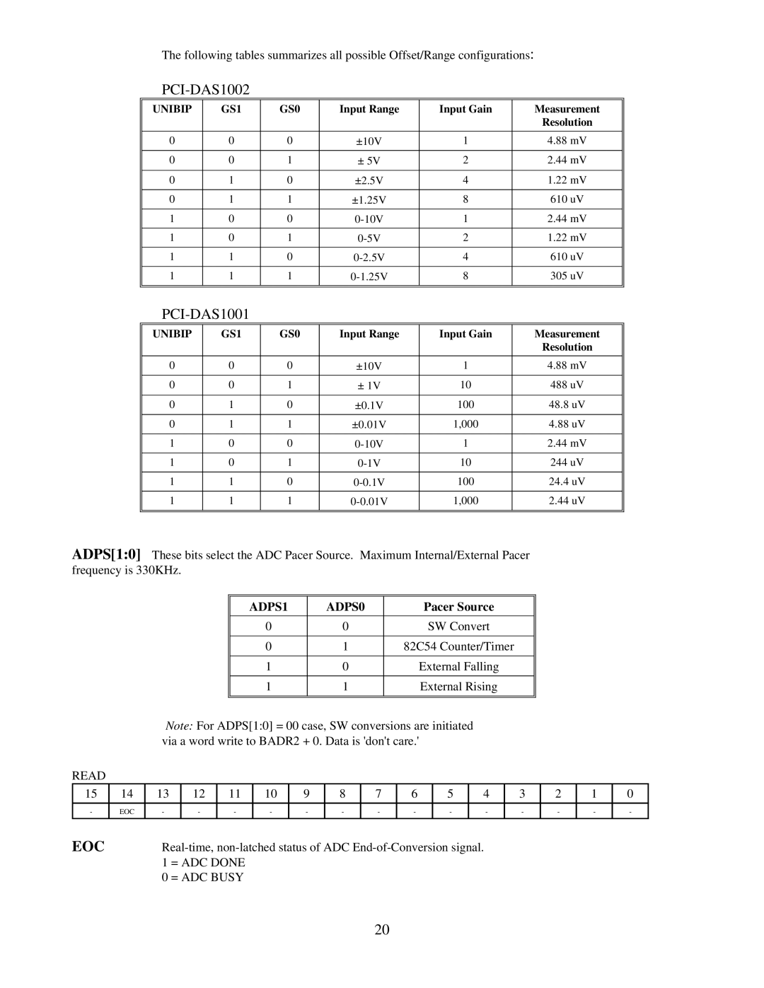
The following tables summarizes all possible Offset/Range configurations:
PCI-DAS1002
UNIBIP | GS1 | GS0 | Input Range | Input Gain | Measurement |
|
|
|
|
| Resolution |
|
|
|
|
|
|
0 | 0 | 0 | ±10V | 1 | 4.88 mV |
|
|
|
|
|
|
0 | 0 | 1 | ± 5V | 2 | 2.44 mV |
|
|
|
|
|
|
0 | 1 | 0 | ±2.5V | 4 | 1.22 mV |
|
|
|
|
|
|
0 | 1 | 1 | ±1.25V | 8 | 610 uV |
|
|
|
|
|
|
1 | 0 | 0 | 1 | 2.44 mV | |
|
|
|
|
|
|
1 | 0 | 1 | 2 | 1.22 mV | |
|
|
|
|
|
|
1 | 1 | 0 | 4 | 610 uV | |
|
|
|
|
|
|
1 | 1 | 1 | 8 | 305 uV | |
|
|
|
|
|
|
|
|
|
|
|
|
PCI-DAS1001
UNIBIP | GS1 | GS0 | Input Range | Input Gain | Measurement |
|
|
|
|
| Resolution |
|
|
|
|
|
|
0 | 0 | 0 | ±10V | 1 | 4.88 mV |
|
|
|
|
|
|
0 | 0 | 1 | ± 1V | 10 | 488 uV |
|
|
|
|
|
|
0 | 1 | 0 | ±0.1V | 100 | 48.8 uV |
|
|
|
|
|
|
0 | 1 | 1 | ±0.01V | 1,000 | 4.88 uV |
|
|
|
|
|
|
1 | 0 | 0 | 1 | 2.44 mV | |
|
|
|
|
|
|
1 | 0 | 1 | 10 | 244 uV | |
|
|
|
|
|
|
1 | 1 | 0 | 100 | 24.4 uV | |
|
|
|
|
|
|
1 | 1 | 1 | 1,000 | 2.44 uV | |
|
|
|
|
|
|
|
|
|
|
|
|
ADPS[1:0] These bits select the ADC Pacer Source. Maximum Internal/External Pacer frequency is 330KHz.
|
|
|
|
|
| ADPS1 |
|
| ADPS0 |
|
|
| Pacer Source |
|
|
|
|
| ||||||
|
|
|
|
|
|
|
|
|
|
|
|
|
|
|
|
|
|
|
|
|
|
|
| |
|
|
|
|
|
| 0 |
|
| 0 |
|
|
|
| SW Convert |
|
|
|
|
| |||||
|
|
|
|
|
|
|
|
|
|
|
|
|
|
|
|
|
|
|
|
|
|
| ||
|
|
|
|
|
| 0 |
|
| 1 |
|
|
| 82C54 Counter/Timer |
|
|
|
|
| ||||||
|
|
|
|
|
|
|
|
|
|
|
|
|
|
|
|
|
|
|
|
|
|
|
| |
|
|
|
|
|
| 1 |
|
| 0 |
|
|
|
| External Falling |
|
|
|
|
| |||||
|
|
|
|
|
|
|
|
|
|
|
|
|
|
|
|
|
|
|
|
|
|
|
| |
|
|
|
|
|
| 1 |
|
| 1 |
|
|
|
| External Rising |
|
|
|
|
| |||||
|
|
|
|
|
|
|
|
|
|
|
|
|
|
|
|
|
|
|
|
|
| |||
|
|
|
|
|
|
|
|
|
|
|
|
|
|
|
|
|
|
|
|
|
|
|
|
|
|
| Note: For ADPS[1:0] = 00 case, SW conversions are initiated |
|
|
|
|
|
|
| |||||||||||||||
|
| via a word write to BADR2 + 0. Data is 'don't care.' |
|
|
|
|
|
|
| |||||||||||||||
READ |
|
|
|
|
|
|
|
|
|
|
|
|
|
|
|
|
|
|
|
|
|
|
|
|
15 | 14 | 13 | 12 |
| 11 |
| 10 | 9 | 8 |
| 7 |
| 6 |
| 5 |
| 4 |
| 3 |
| 2 | 1 | 0 | |
|
|
|
|
|
|
|
|
|
|
|
|
|
|
|
|
|
|
|
|
|
|
|
| |
- | EOC | - | - |
| - |
| - | - | - |
| - |
| - |
| - |
| - |
| - |
| - | - | - | |
|
|
|
|
|
|
|
|
|
|
|
|
|
|
|
|
|
| |||||||
EOC |
|
|
|
|
|
| ||||||||||||||||||
|
| 1 = ADC DONE |
|
|
|
|
|
|
|
|
|
|
|
|
|
|
|
|
|
|
| |||
|
| 0 = ADC BUSY |
|
|
|
|
|
|
|
|
|
|
|
|
|
|
|
|
|
|
| |||
20
