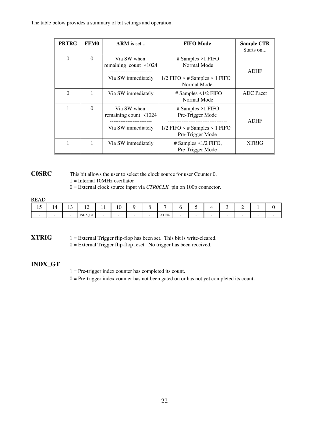
The table below provides a summary of bit settings and operation.
|
|
|
| PRTRG |
| FFM0 |
|
|
| ARM is set... |
|
|
|
| FIFO Mode |
| Sample CTR |
|
| |||||||||||
|
|
|
|
|
|
|
|
|
|
|
|
|
|
|
|
|
|
|
|
|
|
|
|
| Starts on... |
|
| |||
|
|
|
|
|
|
|
|
|
|
|
|
|
|
|
|
|
|
|
|
|
|
|
|
|
|
|
|
|
| |
|
|
|
| 0 |
|
| 0 |
|
|
|
| Via SW when |
|
|
| # Samples >1 FIFO |
|
|
|
|
|
|
| |||||||
|
|
|
|
|
|
|
|
|
|
| remaining count <1024 |
|
| Normal Mode |
|
|
|
|
|
|
| |||||||||
|
|
|
|
|
|
|
|
|
|
|
|
|
| ADHF |
|
| ||||||||||||||
|
|
|
|
|
|
|
|
|
|
|
| Via SW immediately | 1/2 FIFO < # Samples < 1 FIFO |
|
|
|
|
|
| |||||||||||
|
|
|
|
|
|
|
|
|
|
|
|
|
|
|
|
|
|
|
| Normal Mode |
|
|
|
|
|
|
| |||
|
|
|
|
|
|
|
|
|
|
|
|
|
|
|
|
|
|
|
|
|
|
|
|
|
|
|
| |||
|
|
|
| 0 |
|
| 1 |
|
|
| Via SW immediately |
| # Samples <1/2 FIFO |
| ADC Pacer |
|
| |||||||||||||
|
|
|
|
|
|
|
|
|
|
|
|
|
|
|
|
|
|
|
| Normal Mode |
|
|
|
|
|
|
| |||
|
|
|
|
|
|
|
|
|
|
|
|
|
|
|
|
|
|
|
|
|
|
|
|
|
|
|
|
|
| |
|
|
|
| 1 |
|
| 0 |
|
|
|
| Via SW when |
|
|
| # Samples >1 FIFO |
|
|
|
|
|
|
| |||||||
|
|
|
|
|
|
|
|
|
|
| remaining count <1024 |
|
|
|
|
|
|
|
| |||||||||||
|
|
|
|
|
|
|
|
|
|
|
|
|
| ADHF |
|
| ||||||||||||||
|
|
|
|
|
|
|
|
|
|
|
| Via SW immediately | 1/2 FIFO < # Samples < 1 FIFO |
|
|
|
|
|
| |||||||||||
|
|
|
|
|
|
|
|
|
|
|
|
|
|
|
|
|
|
|
|
|
|
|
|
|
| |||||
|
|
|
|
|
|
|
|
|
|
|
|
|
|
|
|
|
|
|
|
|
|
|
|
|
|
|
|
| ||
|
|
|
| 1 |
|
| 1 |
|
|
| Via SW immediately |
| # Samples <1/2 FIFO, |
|
| XTRIG |
|
| ||||||||||||
|
|
|
|
|
|
|
|
|
|
|
|
|
|
|
|
|
|
|
|
|
|
|
|
|
| |||||
C0SRC |
|
|
|
|
|
|
|
|
|
|
|
|
|
|
|
|
|
|
|
|
|
|
|
|
| |||||
|
|
|
|
|
|
|
|
|
|
|
|
|
|
|
|
|
|
|
|
|
|
|
|
|
|
|
|
| ||
|
|
|
| This bit allows the user to select the clock source for user Counter 0. |
|
|
|
|
|
|
| |||||||||||||||||||
|
|
|
|
|
| 1 = Internal 10MHz oscillator |
|
|
|
|
|
|
|
|
|
|
|
|
|
|
| |||||||||
|
|
|
|
|
| 0 = External clock source input via CTR0CLK pin on 100p connector. |
|
|
|
|
|
|
| |||||||||||||||||
READ |
|
|
|
|
|
|
|
|
|
|
|
|
|
|
|
|
|
|
|
|
|
|
|
|
|
|
|
|
| |
15 |
| 14 |
| 13 | 12 |
| 11 |
| 10 | 9 |
| 8 |
| 7 | 6 |
| 5 | 4 |
| 3 | 2 |
| 1 |
| 0 |
| ||||
|
|
|
|
|
|
|
|
|
|
|
|
|
|
|
|
|
|
|
|
|
|
|
|
|
|
|
| |||
- |
| - |
|
| - | INDX_GT |
| - |
| - | - |
| - |
| XTRIG | - |
| - | - |
| - | - |
| - |
| - |
| |||
|
|
|
|
|
|
|
|
|
|
|
|
|
|
|
|
|
|
|
|
|
| |||||||||
XTRIG |
|
| 1 = External Trigger |
|
|
|
|
|
|
| ||||||||||||||||||||
|
|
|
|
|
| 0 = External Trigger |
|
|
|
|
|
|
| |||||||||||||||||
INDX_GT
1 =
0 =
22