+13V |
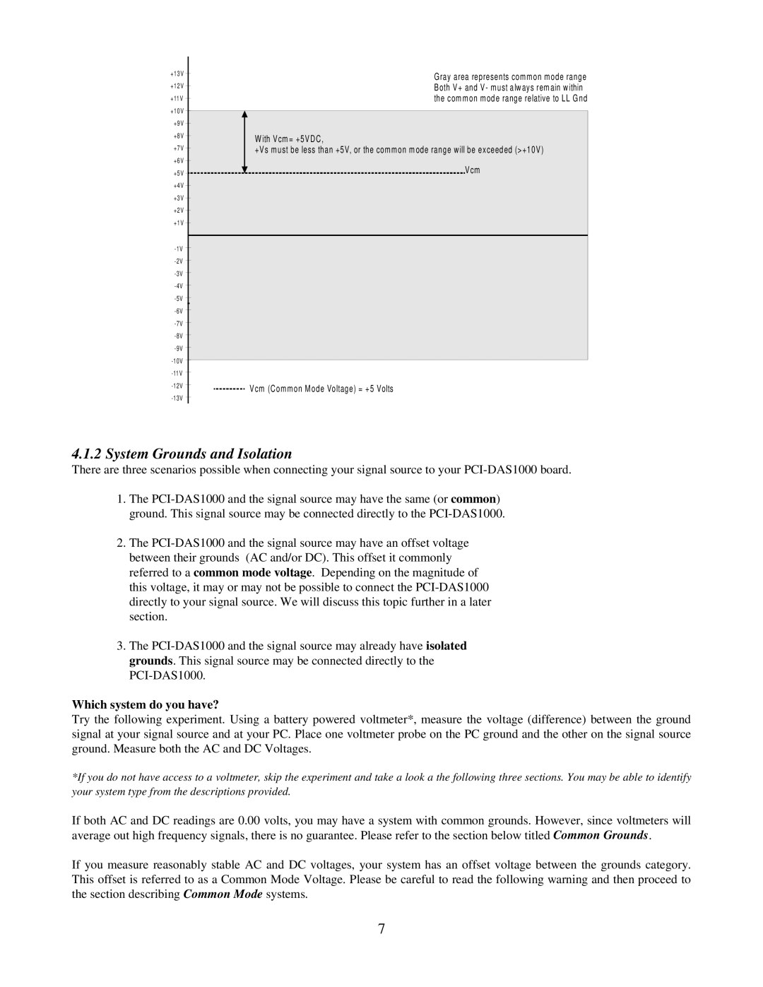
| Gray area represents common mode range | |
| |||
|
|
| |
+12V |
| Both V+ and V- must always remain within | |
| |||
+11V |
| the common mode range relative to LL Gnd | |
| |||
+10V |
|
| |
+9V |
|
| |
|
| ||
+8V |
| With Vcm= +5VDC, | |
| |||
+7V |
|
| |
| +Vs must be less than +5V, or the common mode range will be exceeded (>+10V) | ||
| |||
+6V |
| Vcm | |
| |||
+5V | |||
+4V |
|
| |
|
| ||
+3V |
|
| |
|
| ||
+2V |
|
| |
|
| ||
+1V |
|
| |
|
| ||
|
| ||
|
| ||
|
| ||
|
| ||
|
| ||
|
| ||
|
| ||
|
| ||
|
| ||
|
| ||
|
| ||
|
| ||
|
| ||
|
| ||
|
| ||
|
| ||
|
| ||
|
| ||
|
| ||
|
| ||
|
| ||
|
| ||
| Vcm (Common Mode Voltage) = +5 Volts | ||
| |||
|
|
| |
4.1.2System Grounds and Isolation
There are three scenarios possible when connecting your signal source to your
1.The
2.The
3.The
Which system do you have?
Try the following experiment. Using a battery powered voltmeter*, measure the voltage (difference) between the ground signal at your signal source and at your PC. Place one voltmeter probe on the PC ground and the other on the signal source ground. Measure both the AC and DC Voltages.
*If you do not have access to a voltmeter, skip the experiment and take a look a the following three sections. You may be able to identify your system type from the descriptions provided.
If both AC and DC readings are 0.00 volts, you may have a system with common grounds. However, since voltmeters will average out high frequency signals, there is no guarantee. Please refer to the section below titled Common Grounds.
If you measure reasonably stable AC and DC voltages, your system has an offset voltage between the grounds category. This offset is referred to as a Common Mode Voltage. Please be careful to read the following warning and then proceed to the section describing Common Mode systems.
7
