7.5.3 INDEX and USER COUNTER 4 DATA AND CONTROL REGISTERS
8254B COUNTER 0 DATA - ADC
BADR3 + 8
READ/WRITE
7 | 6 | 5 | 4 | 2 | 3 | 1 | 0 |
|
|
|
|
|
|
|
|
D7 | D6 | D5 | D4 | D3 | D2 | D1 | D0 |
|
|
|
|
|
|
|
|
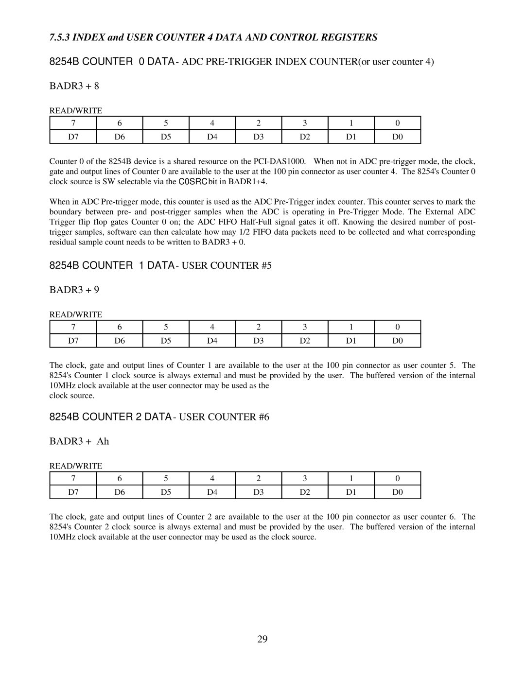
Counter 0 of the 8254B device is a shared resource on the
When in ADC
8254B COUNTER 1 DATA - USER COUNTER #5
BADR3 + 9
READ/WRITE
7 | 6 | 5 | 4 | 2 | 3 | 1 | 0 |
|
|
|
|
|
|
|
|
D7 | D6 | D5 | D4 | D3 | D2 | D1 | D0 |
|
|
|
|
|
|
|
|
The clock, gate and output lines of Counter 1 are available to the user at the 100 pin connector as user counter 5. The 8254's Counter 1 clock source is always external and must be provided by the user. The buffered version of the internal 10MHz clock available at the user connector may be used as the
clock source.
8254B COUNTER 2 DATA - USER COUNTER #6
BADR3 + Ah
READ/WRITE
7 | 6 | 5 | 4 | 2 | 3 | 1 | 0 |
|
|
|
|
|
|
|
|
D7 | D6 | D5 | D4 | D3 | D2 | D1 | D0 |
|
|
|
|
|
|
|
|
The clock, gate and output lines of Counter 2 are available to the user at the 100 pin connector as user counter 6. The 8254's Counter 2 clock source is always external and must be provided by the user. The buffered version of the internal 10MHz clock available at the user connector may be used as the clock source.
29
