4.0 ANALOG CONNECTIONS

4.1 ANALOG INPUTS

Analog signal connection is one of the most challenging aspects of applying a data acquisition board. If you are an Analog Electrical Engineer then this section is not for you, but if you are like most PC data acquisition users, the best way to connect your analog inputs may not be obvious. Though complete coverage of this topic is well beyond the scope of this manual, the following section provides some explanations and helpful hints regarding these analog input connections. This section is designed to help you achieve the optimum performance from your PCI-DAS1000 series board.

Prior to jumping into actual connection schemes, you should have at least a basic understanding of Single-Ended/Differen- tial inputs and system grounding/isolation. If you are already comfortable with these concepts you may wish to skip to the next section (on wiring configurations).

4.1.1 Single-Ended and Differential Inputs

The PCI-DAS1000 provides either 8 differential or 16 single-ended input channels. The concepts of single-ended and differential inputs are discussed in the following section.

Single-Ended Inputs

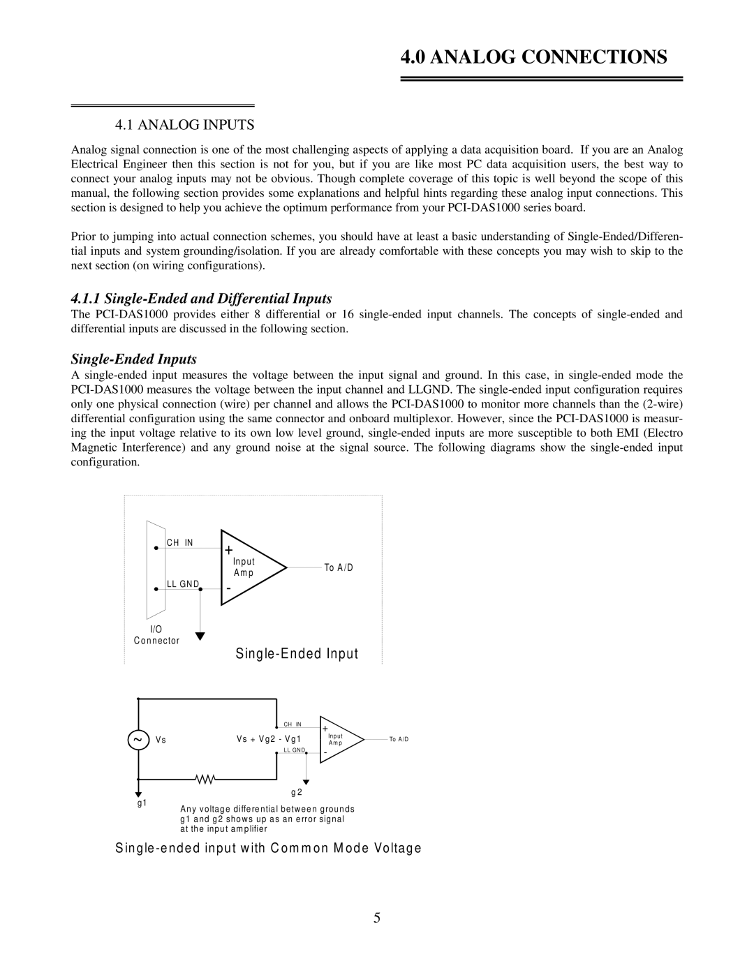
A single-ended input measures the voltage between the input signal and ground. In this case, in single-ended mode the PCI-DAS1000 measures the voltage between the input channel and LLGND. The single-ended input configuration requires only one physical connection (wire) per channel and allows the PCI-DAS1000 to monitor more channels than the (2-wire) differential configuration using the same connector and onboard multiplexor. However, since the PCI-DAS1000 is measur- ing the input voltage relative to its own low level ground, single-ended inputs are more susceptible to both EMI (Electro Magnetic Interference) and any ground noise at the signal source. The following diagrams show the single-ended input configuration.

CH IN

LL GND

I/O

C onnector

+

In p ut


To A /D

A m p


-

Single-Ended Input


CH IN

+


~


V s

Vs + V g2 - V g1

Inp ut


To A /D

A m p


LL GN D

-


g1

g 2

An y voltage differential betw een grounds g1 and g2 show s up as an error signal at the input am plifier

S in gle -ended input w ith C om m on M ode Voltage

5

Page 8
Image 8
Omega Speaker Systems PCI-DAS1002 manual Analog Connections, Single-Ended and Differential Inputs, Single-Ended Inputs