3.0 HARDWARE CONNECTIONS
3.1 CONNECTOR PIN DIAGRAM
The
wiring error is found.
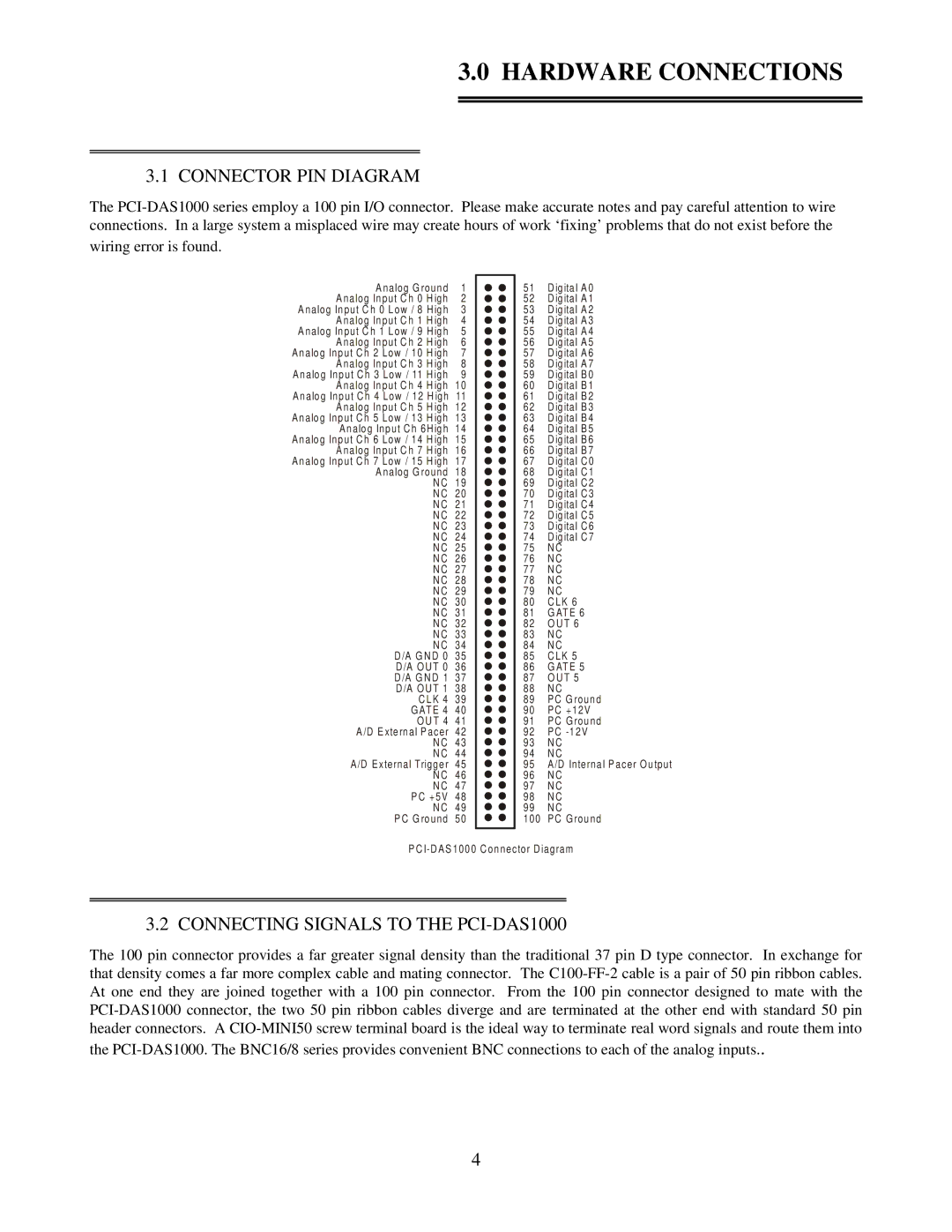
Analog G round | 1 | 51 | D igital A0 |
Analog Input C h 0 H igh | 2 | 52 | D igital A1 |
Analog Input C h 0 Low / 8 H igh | 3 | 53 | D igital A2 |
Analog Input C h 1 H igh | 4 | 54 | D igital A3 |
Analog Input C h 1 Low / 9 H igh | 5 | 55 | D igital A4 |
Analog Input C h 2 H igh | 6 | 56 | D igital A5 |
Analog Input C h 2 Low / 10 H igh | 7 | 57 | D igital A6 |
Analog Input C h 3 H igh | 8 | 58 | D igital A7 |
Analog Input C h 3 Low / 11 H igh | 9 | 59 | D igital B0 |
Analog Input C h 4 H igh | 10 | 60 | D igital B1 |
Analog Input C h 4 Low / 12 H igh | 11 | 61 | D igital B2 |
Analog Input C h 5 H igh | 12 | 62 | D igital B3 |
Analog Input C h 5 Low / 13 H igh | 13 | 63 | D igital B4 |
Analog Input C h 6H igh | 14 | 64 | D igital B5 |
Analog Input C h 6 Low / 14 H igh | 15 | 65 | D igital B6 |
Analog Input C h 7 H igh | 16 | 66 | D igital B7 |
Analog Input C h 7 Low / 15 H igh | 17 | 67 | D igital C 0 |
Analog G round | 18 | 68 | D igital C 1 |
N C | 19 | 69 | D igital C 2 |
N C | 20 | 70 | D igital C 3 |
N C | 21 | 71 | D igital C 4 |
N C | 22 | 72 | D igital C 5 |
N C | 23 | 73 | D igital C 6 |
N C | 24 | 74 | D igital C 7 |
N C | 25 | 75 | N C |
N C | 26 | 76 | N C |
N C | 27 | 77 | N C |
N C | 28 | 78 | N C |
N C | 29 | 79 | N C |
N C | 30 | 80 | C LK 6 |
N C | 31 | 81 | G ATE 6 |
N C | 32 | 82 | O U T 6 |
N C | 33 | 83 | N C |
N C | 34 | 84 | N C |
D /A G N D 0 | 35 | 85 | C LK 5 |
D /A O U T 0 | 36 | 86 | G ATE 5 |
D /A G N D 1 37 | 87 | O U T 5 | |
D /A O U T 1 | 38 | 88 | N C |
C LK 4 | 39 | 89 | PC G round |
G ATE 4 | 40 | 90 | PC +12V |
O U T 4 | 41 | 91 | PC G round |
A/D External Pacer | 42 | 92 | PC |
N C | 43 | 93 | N C |
N C | 44 | 94 | N C |
A/D External Trigger | 45 | 95 | A/D Internal Pacer O utput |
N C | 46 | 96 | N C |
N C | 47 | 97 | N C |
PC +5V | 48 | 98 | N C |
N C | 49 | 99 | N C |
PC G round | 50 | 100 | PC G round |
PC
3.2 CONNECTING SIGNALS TO THE PCI-DAS1000
The 100 pin connector provides a far greater signal density than the traditional 37 pin D type connector. In exchange for that density comes a far more complex cable and mating connector. The
4