WIRE CONNECTIONS
DC Wiring
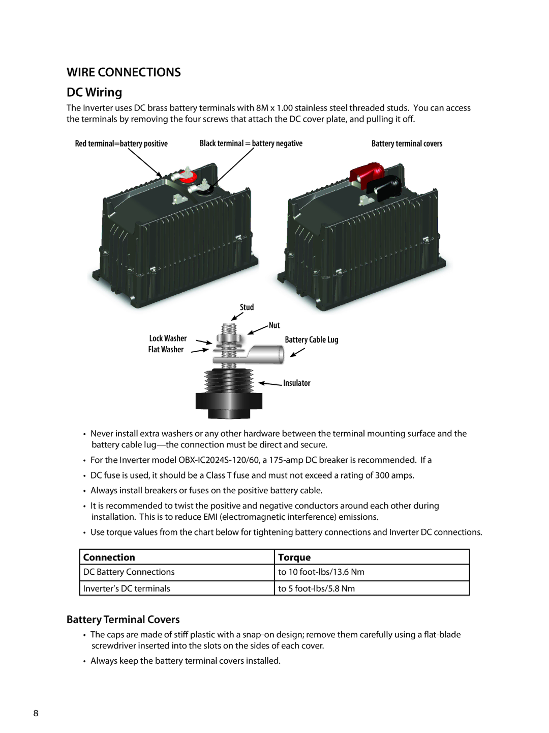
The Inverter uses DC brass battery terminals with 8M x 1.00 stainless steel threaded studs. You can access the terminals by removing the four screws that attach the DC cover plate, and pulling it off.
Red terminal=battery positive | Black terminal = battery negative | Battery terminal covers |
| Stud |
| Nut |
Lock Washer | Battery Cable Lug |
Flat Washer |
|
| Insulator |
•Never install extra washers or any other hardware between the terminal mounting surface and the battery cable
•For the Inverter model
•DC fuse is used, it should be a Class T fuse and must not exceed a rating of 300 amps.
•Always install breakers or fuses on the positive battery cable.
•It is recommended to twist the positive and negative conductors around each other during installation. This is to reduce EMI (electromagnetic interference) emissions.
•Use torque values from the chart below for tightening battery connections and Inverter DC connections.
Connection | Torque |
DC Battery Connections | to 10 |
|
|
Inverter’s DC terminals | to 5 |
Battery Terminal Covers
• The caps are made of stiff plastic with a
•Always keep the battery terminal covers installed.
8