Parts and their functions
|
|
|
| AUDIO IN |
|
|
|
L | R | L | R | L | R | L | R |
1 | 2 | 3 | 4 |
1 | 2 | 3 | 4 |
AUDIO OUT 1
LR
5
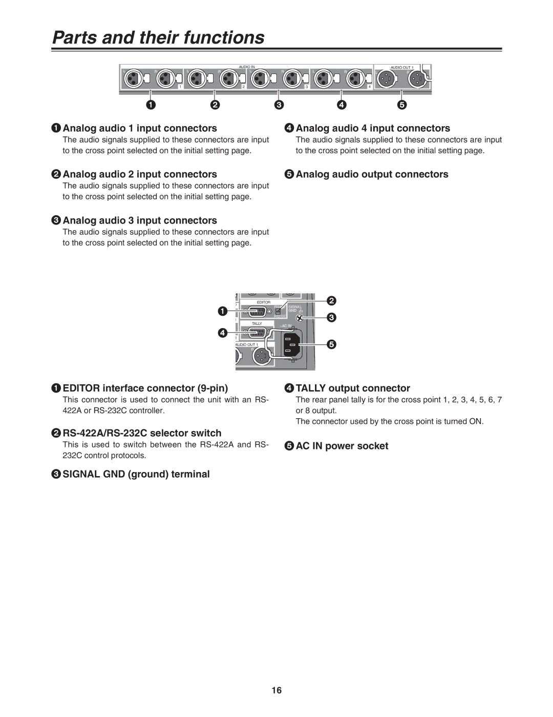
1Analog audio 1 input connectors | 4Analog audio 4 input connectors |
The audio signals supplied to these connectors are input to the cross point selected on the initial setting page.
The audio signals supplied to these connectors are input to the cross point selected on the initial setting page.
2Analog audio 2 input connectors | 5Analog audio output connectors |
The audio signals supplied to these connectors are input to the cross point selected on the initial setting page.
3Analog audio 3 input connectors
The audio signals supplied to these connectors are input to the cross point selected on the initial setting page.
O | EDITOR | RS422 | 2 |
1 |
| SIGNAL | |
|
| GND | |
1 |
|
| |
| RS232C | 3 | |
| TALLY | ~AC IN | |
|
| ||
4 |
|
|
|
2 |
|
| 5 |
AUDIO OUT 1 |
| ||
| R |
|
|
1EDITOR interface connector (9-pin)
This connector is used to connect the unit with an RS- 422A or
4TALLY output connector
The rear panel tally is for the cross point 1, 2, 3, 4, 5, 6, 7 or 8 output.
The connector used by the cross point is turned ON.
2RS-422A/RS-232C selector switch
This is used to switch between the
3SIGNAL GND (ground) terminal
16