System Diagram
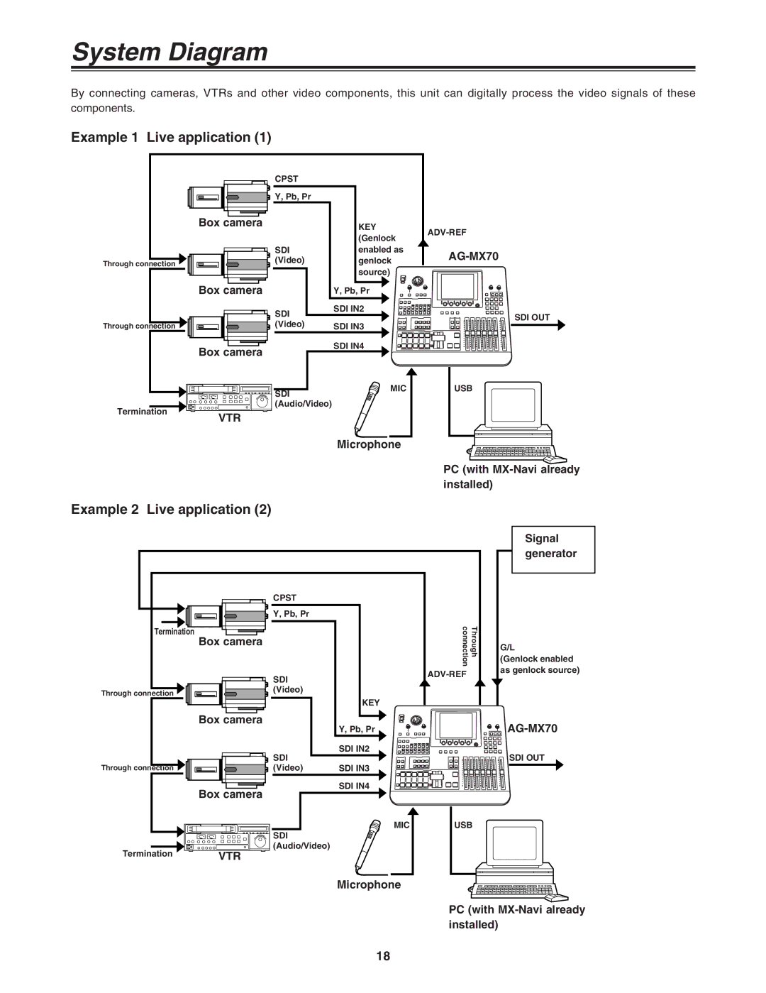
By connecting cameras, VTRs and other video components, this unit can digitally process the video signals of these components.
Example 1 Live application (1)
Box camera
Through connection ![]()
Box camera
Through connection ![]()
Box camera
Termination
VTR
CPST
Y, Pb, Pr
| KEY |
| (Genlock |
SDI | enabled as |
(Video) | genlock |
| source) |
| Y, Pb, Pr |
SDI | SDI IN2 |
| |
(Video) | SDI IN3 |
| SDI IN4 |
SDI | MIC |
| |
(Audio/Video) |
|
SDI OUT
USB
Microphone
Example 2 Live application (2)
PC (with
|
| CPST |
|
|
| Y, Pb, Pr |
|
Termination | Box camera |
| Through connection |
|
| ||
|
|
| |
|
| SDI | |
|
|
| |
Through connection |
| (Video) |
|
|
| KEY | |
|
|
|
|
|
|
| Box camera |
|
|
|
| ||||||||
|
|
|
|
| Y, Pb, Pr |
| ||||||||||
|
|
|
|
|
|
|
|
|
|
|
|
|
| |||
|
|
|
|
|
|
|
|
|
|
|
| SDI |
| SDI IN2 | ||
Through connection |
|
|
|
|
|
|
|
|
|
| (Video) |
| SDI IN3 | |||
|
|
|
|
|
|
|
|
|
|
|
|
|
|
|
|
|
|
|
|
|
|
|
|
|
|
|
|
|
|
| SDI IN4 | ||
|
|
|
|
|
|
|
|
|
|
|
|
| ||||
Box camera
| MIC | USB |
| SDI |
|
Termination | (Audio/Video) |
|
VTR |
|
Signal generator
G/L
(Genlock enabled as genlock source)
![]()
![]()
SDI OUT
Microphone
PC (with
18