System Diagram
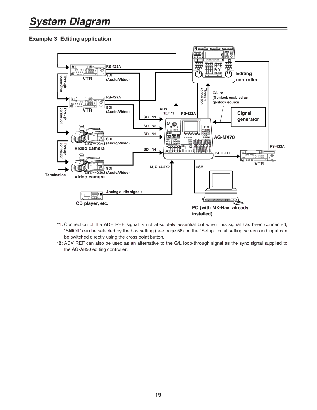
Example 3 Editing application
connection | Through |
connection | Through |
connection | Through |
Termination
|
|
| ||
VTR | SDI |
|
| |
(Audio/Video) |
|
| ||
|
| Through connection | ||
|
|
| ||
VTR | SDI | ADV |
| |
(Audio/Video) |
| |||
REF *1 | ||||
|
| |||
|
| SDI IN1 |
| |
|
| SDI IN2 |
| |
|
| SDI IN3 |
| |
| SDI |
|
| |
| (Audio/Video) |
|
| |
Video camera |
| SDI IN4 |
| |
| SDI | AUX1/AUX2 | USB | |
|
|
| ||
Video camera | (Audio/Video) |
|
| |
|
|
| ||
| Analog audio signals |
|
|
Editing controller
G/L *2
(Genlock enabled as genlock source)
Signal generator
SDI OUT
VTR
CD player, etc.
PC (with MX-Navi already installed)
*1: Connection of the ADF REF signal is not absolutely essential but when this signal has been connected, “StillOff” can be selected by the bus setting (see page 56) on the “Setup” initial setting screen and input can be switched directly using the cross point button.
*2: ADV REF can also be used as an alternative to the G/L
19