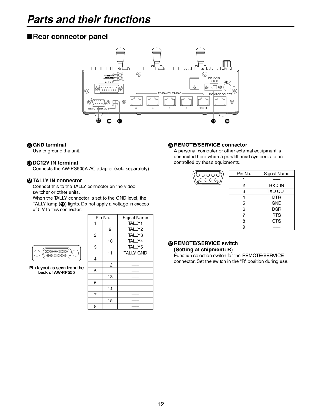
AW-RP555N specifications
The Panasonic AW-RP555N is a sophisticated camera controller designed to streamline remote production and broadcasting operations. This advanced controller is equipped with cutting-edge technology, making it a preferred choice among professionals in the media and entertainment industry.One of the standout features of the AW-RP555N is its support for IP control. The device seamlessly integrates with Panasonic’s line of PTZ (pan-tilt-zoom) cameras, allowing users to operate and manage multiple cameras from a single location. This capability is especially valuable in live event coverage and studio environments, where quick adjustments and precise control are essential.
The AW-RP555N boasts a user-friendly interface that includes an intuitive joystick for easy camera maneuvering. This joystick enables smooth transitions and precise positioning, crucial for capturing dynamic scenes. The device also features programmable presets, allowing operators to save specific camera angles and movements, which can be recalled instantly at the touch of a button. This functionality enhances efficiency and ensures consistency during productions.
Additionally, the AW-RP555N supports various video formats, including 4K quality, ensuring high-resolution output that meets industry standards. The controller is designed for reliability and performance, featuring a robust design that withstands the rigors of daily use in demanding environments.
The integration of advanced networking capabilities in the AW-RP555N uses NDI (Network Device Interface) technology, which enables low-latency, high-quality video transmission over IP networks. This not only simplifies the setup but also reduces the amount of cabling required, providing flexibility in how systems can be configured and expanded.
Furthermore, the device offers multi-camera control, empowering operators to manage up to 100 cameras simultaneously within a network. This feature is particularly advantageous for large productions where multiple angles are needed for comprehensive coverage.
In summary, the Panasonic AW-RP555N is a powerful camera controller that combines user-friendly design with advanced features and networking capabilities. Its ability to handle multiple cameras, along with high-resolution output and IP integration, makes it an essential tool for a wide range of professional video applications. Whether in live broadcasts, corporate events, or studio environments, the AW-RP555N ensures captivating and efficient media production.

