Getting Started
Description of Parts
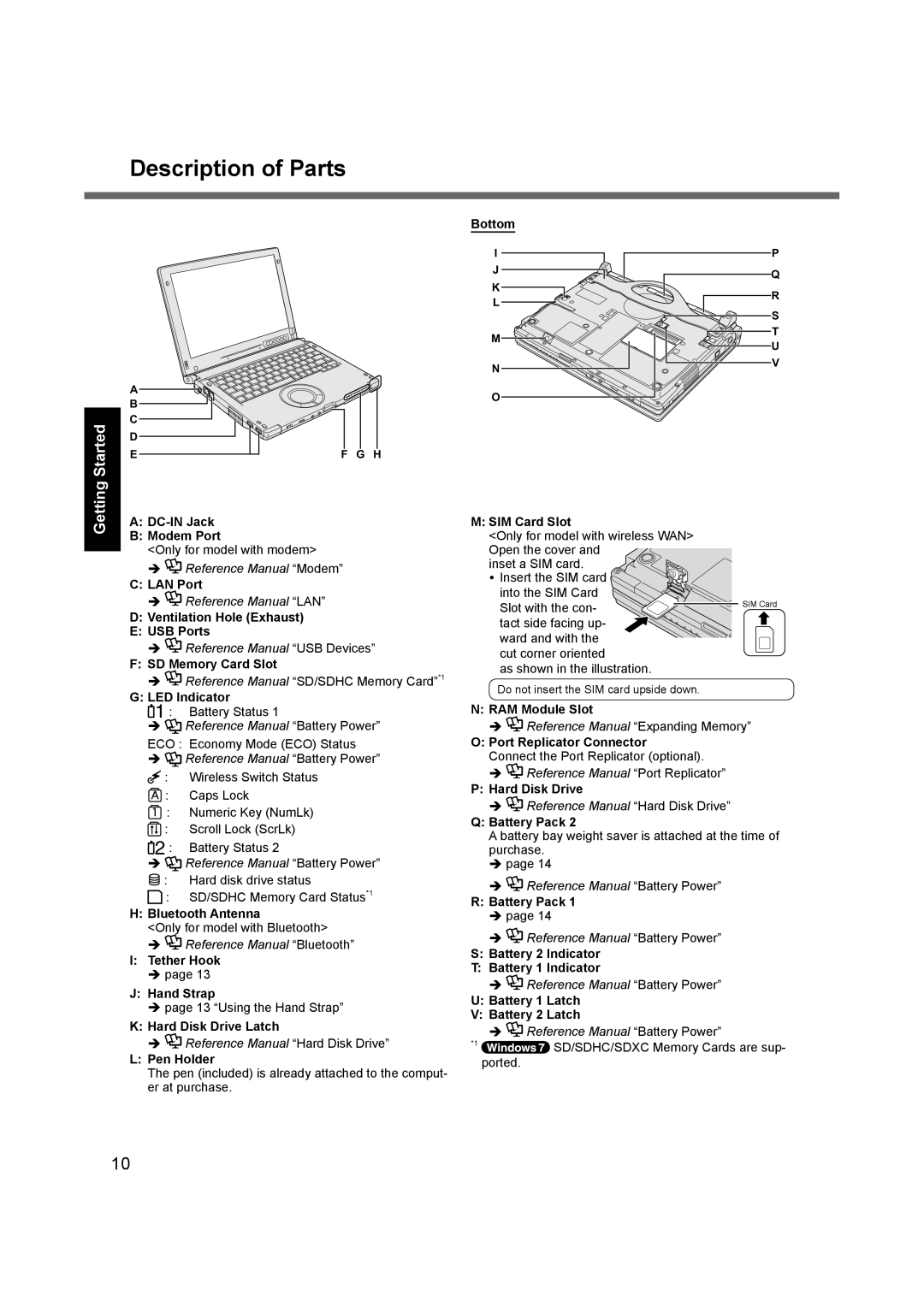
A
B
C
D
E | F G H |
Bottom
I
J
K
L
M |
N |
O |
P
Q
R
S T U V
A:
B:Modem Port
<Only for model with modem>
![]() Reference Manual “Modem”
Reference Manual “Modem”
C: LAN Port
![]() Reference Manual “LAN”
Reference Manual “LAN”
D:Ventilation Hole (Exhaust)
E:USB Ports
![]() Reference Manual “USB Devices”
Reference Manual “USB Devices”
F: SD Memory Card Slot
![]() Reference Manual “SD/SDHC Memory Card”*1
Reference Manual “SD/SDHC Memory Card”*1
G:LED Indicator
![]() 1 : Battery Status 1
1 : Battery Status 1
![]() Reference Manual “Battery Power” ECO : Economy Mode (ECO) Status
Reference Manual “Battery Power” ECO : Economy Mode (ECO) Status
![]() Reference Manual “Battery Power”
Reference Manual “Battery Power”
![]() : Wireless Switch Status
: Wireless Switch Status
![]() : Caps Lock
: Caps Lock
![]() : Numeric Key (NumLk)
: Numeric Key (NumLk)
![]() : Scroll Lock (ScrLk)
: Scroll Lock (ScrLk)
![]() 2 : Battery Status 2
2 : Battery Status 2
Reference Manual “Battery Power”
![]() : Hard disk drive status
: Hard disk drive status
![]() : SD/SDHC Memory Card Status*1
: SD/SDHC Memory Card Status*1
H:Bluetooth Antenna
<Only for model with Bluetooth>
![]() Reference Manual “Bluetooth”
Reference Manual “Bluetooth”
I:Tether Hook
page 13
J: Hand Strap
page 13 “Using the Hand Strap”
K: Hard Disk Drive Latch
![]() Reference Manual “Hard Disk Drive”
Reference Manual “Hard Disk Drive”
L:Pen Holder
The pen (included) is already attached to the comput- er at purchase.
M: SIM Card Slot
<Only for model with wireless WAN> Open the cover and
inset a SIM card. ![]() Insert the SIM card
Insert the SIM card ![]() into the SIM Card
into the SIM Card
Slot with the con- | SIM Card |
|
tact side facing up- ward and with the cut corner oriented
as shown in the illustration.
Do not insert the SIM card upside down.
N: RAM Module Slot
![]() Reference Manual “Expanding Memory”
Reference Manual “Expanding Memory”
O:Port Replicator Connector
Connect the Port Replicator (optional).
![]() Reference Manual “Port Replicator”
Reference Manual “Port Replicator”
P:Hard Disk Drive
![]() Reference Manual “Hard Disk Drive”
Reference Manual “Hard Disk Drive”
Q:Battery Pack 2
A battery bay weight saver is attached at the time of purchase.
page 14
![]() Reference Manual “Battery Power”
Reference Manual “Battery Power”
R:Battery Pack 1 page 14
![]() Reference Manual “Battery Power”
Reference Manual “Battery Power”
S:Battery 2 Indicator
T:Battery 1 Indicator
![]() Reference Manual “Battery Power”
Reference Manual “Battery Power”
U:Battery 1 Latch
V:Battery 2 Latch
![]() Reference Manual “Battery Power”
Reference Manual “Battery Power”
*1 | SD/SDHC/SDXC Memory Cards are sup- |
| |
| ported. |
10
